5 Tutorial 5 – Using Multiple Build Plates
Using Multiple Build Plates
Amanda Shepp and Christopher Shepp
Hello, and welcome to Re3D 3D printing Tutorial 5. In this tutorial we will be processing a large, multi-part print that needs to be submitted in multiple requests. We will be using some intermediate features of MakerBot Print to rearrange, resize, and re-orient multiple parts onto multiple build plates. This tutorial is meant to follow Re3D Tutorials 1-4 and builds on the knowledge discussed in them. The 3D model file we will be using in this tutorial can be found here.
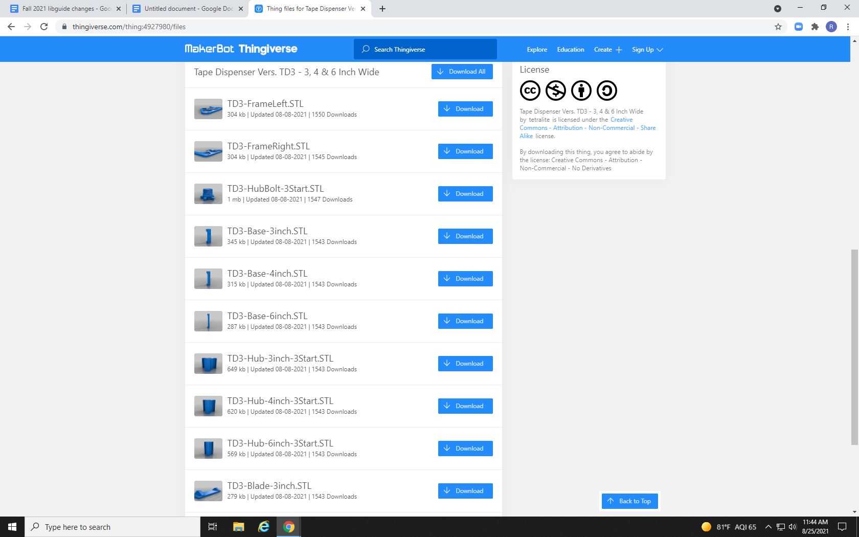
Some 3D prints you may come across are more like projects than simple one-part models. These files will come with a large number of separate files, often including multiple versions of the same part for different sizes or different variations. The file we are looking at, for example, contains a few parts for three-, four-, and five-inch tape rolls.

By clicking the download button to the right of each individual part, users can download only the parts they need. For example, Re3D uses book tape to add texture to the MakerBot’s build plate to increase the adhesion of the melted filament, and to prevent parts from peeling off the build plate and warping as they dry. My roll of book tape is just under 3 inches wide, so we will be printing for that size.
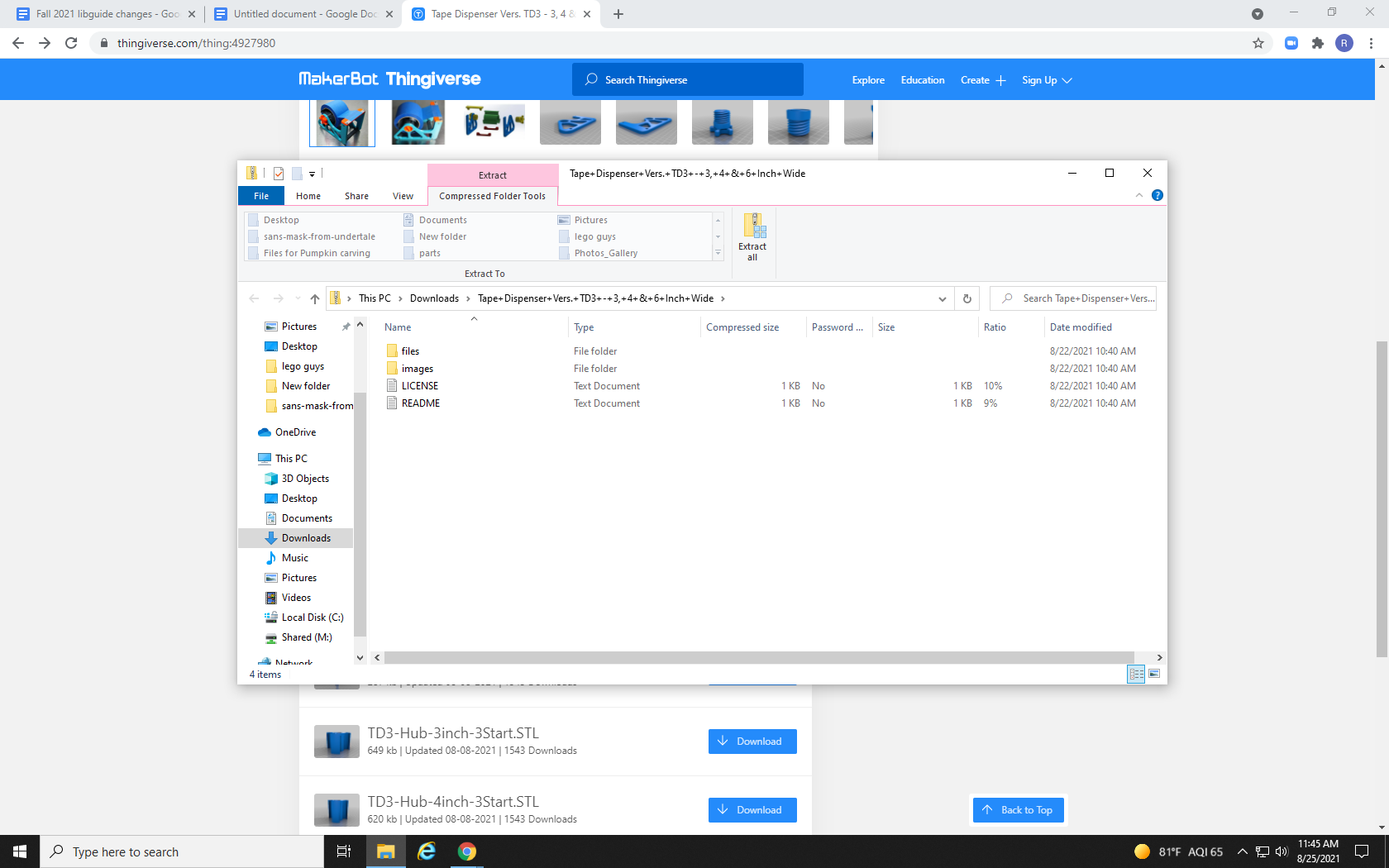
However, with this many files, it can sometimes be easier to use the “Download All” button. This will download the entire list of files in a zipped folder.
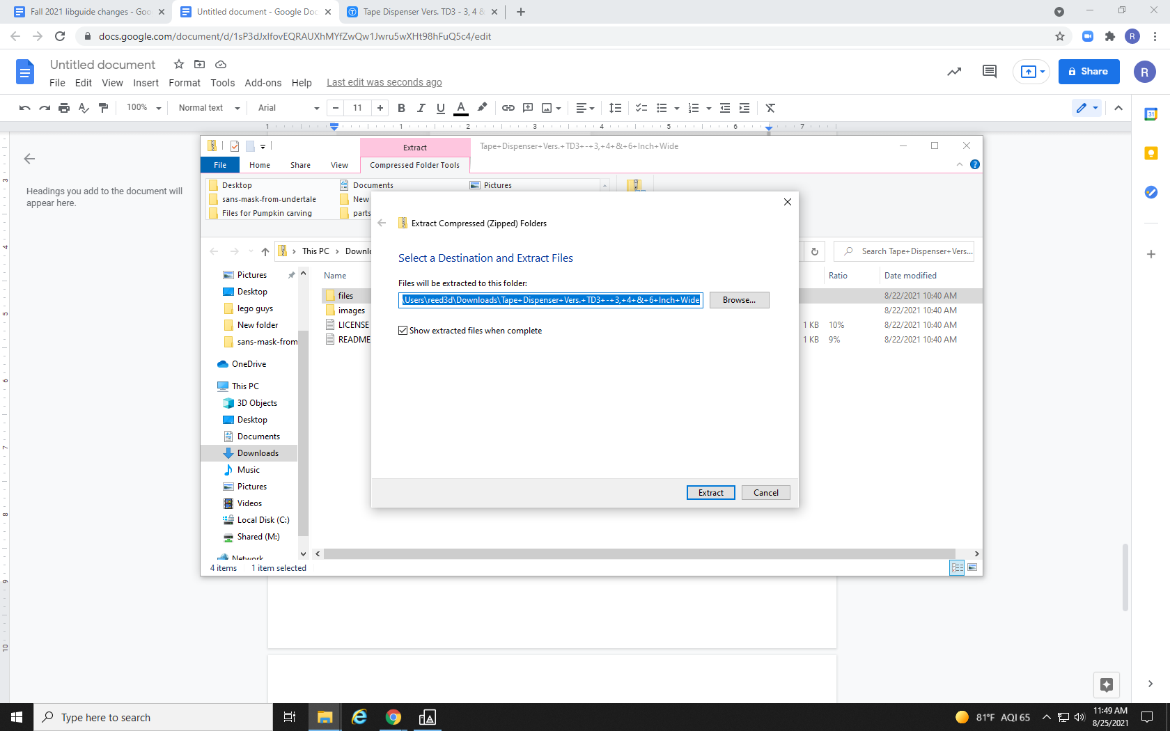
Open the zipped file in your preferred unzipping software, and select “Extract All.”
The default location it will unzip to is the same place the zipped file downloaded to, but Re3D recommends using the “Browse” option to save the unzipped files in a location where they will be easy to find, such as a new file folder on your desktop.
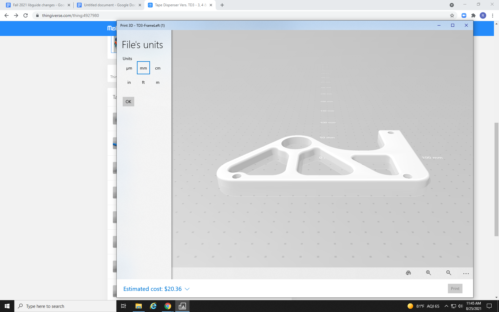
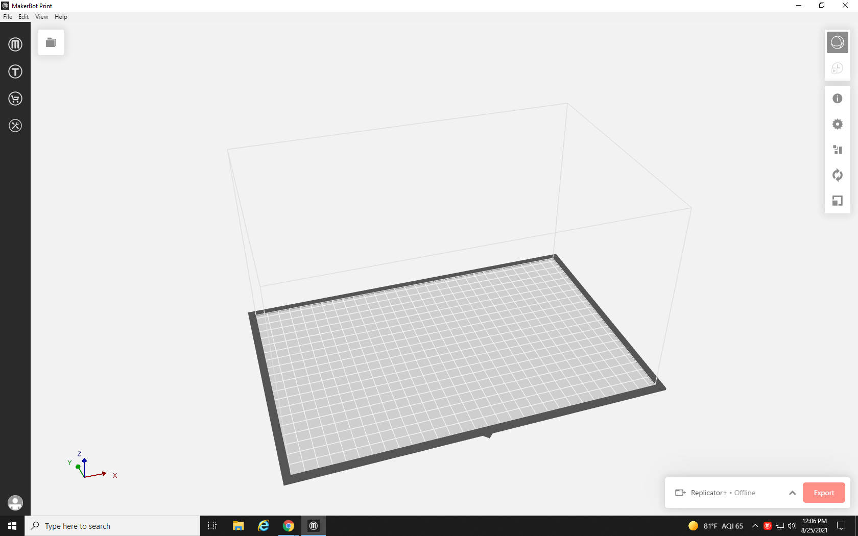
With your files unzipped in a location that you will remember, go ahead and open a new project in Makerbot Print.
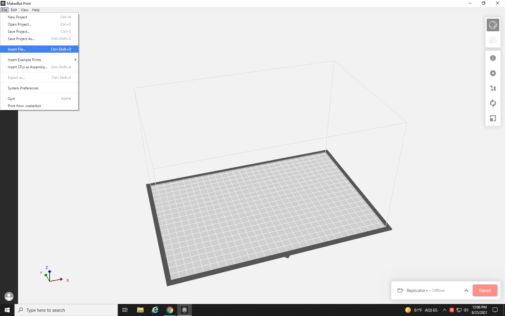
Click the File menu in the toolbar and select “Insert File,” just as we did for the simple single-part print in Tutorial 2.
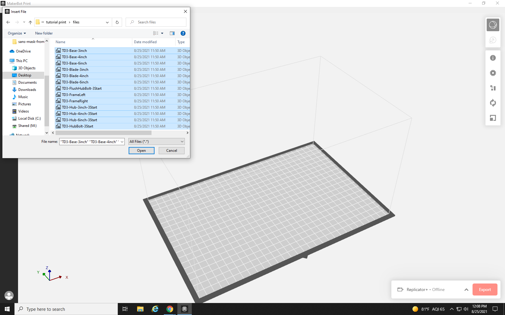
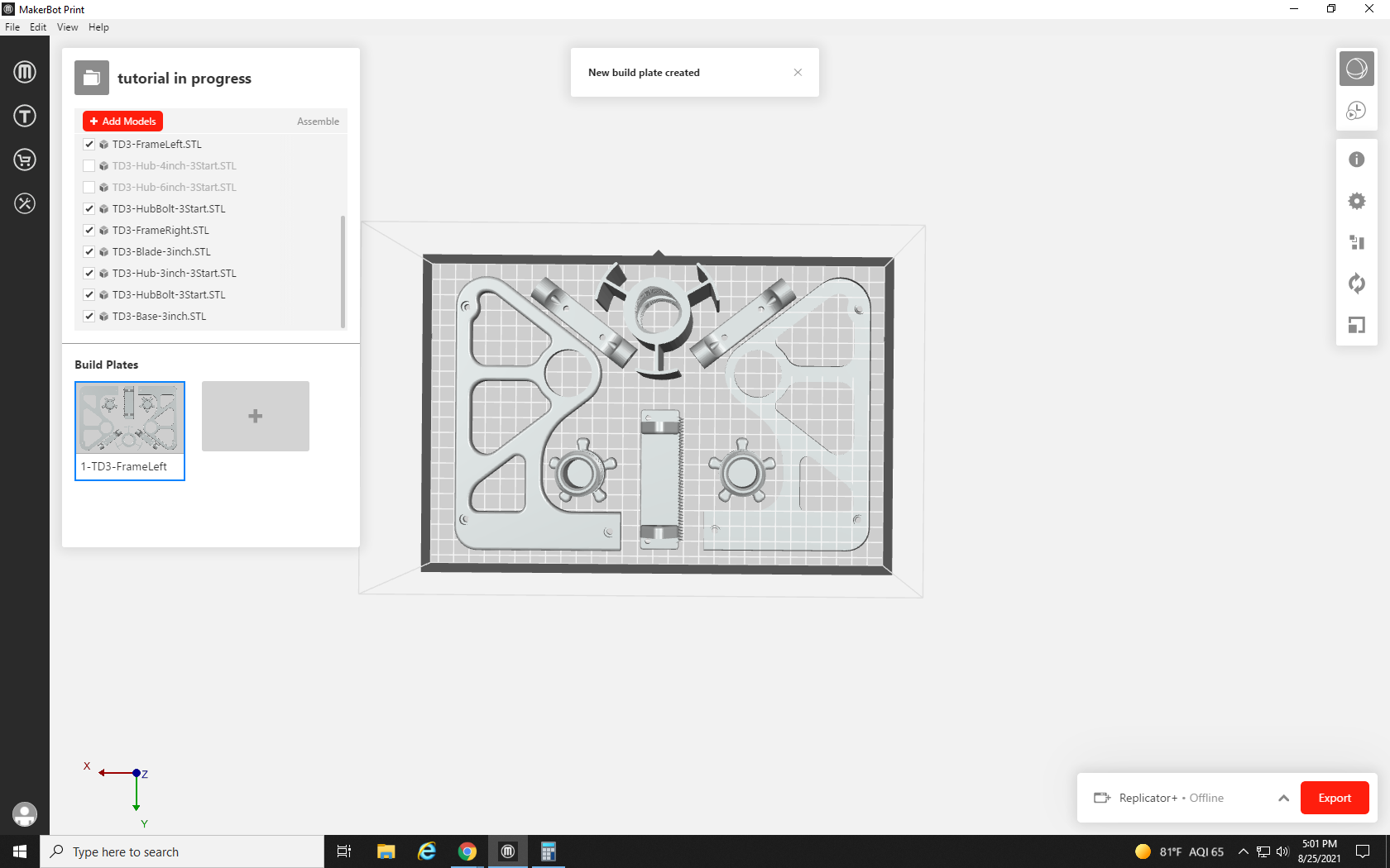
Navigate in the file browser to the folder where you unzipped your print files, and select them all by clicking once on the top .stl file and then holding the Shift key and down arrow on your keyboard until all the files are highlighted, and click Open.
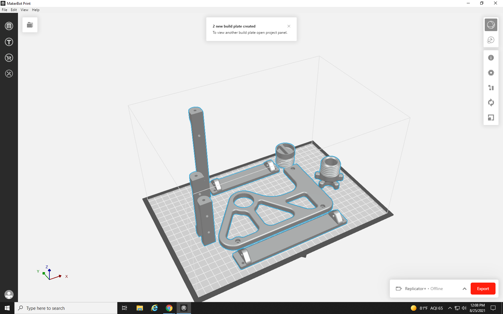
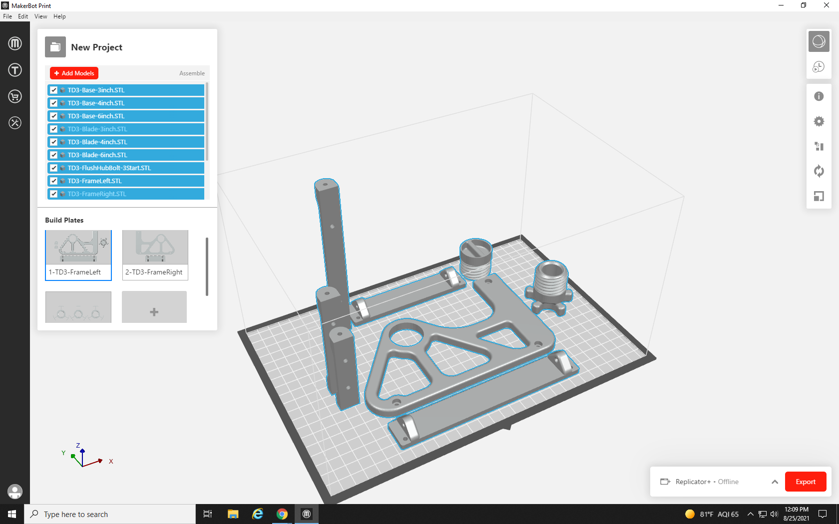
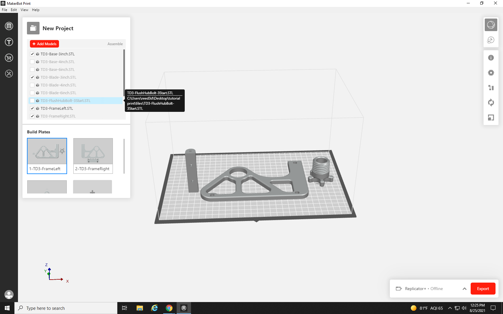
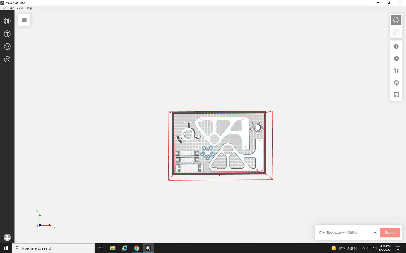
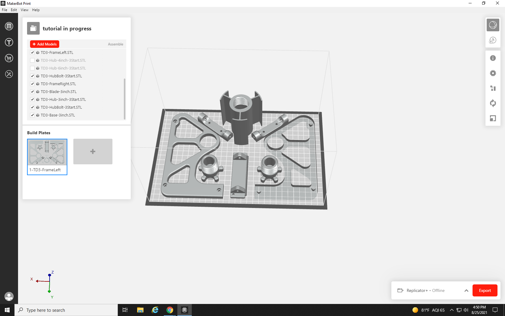
MakerBot Print automatically arranges the parts on the build plate, but it is not always the best or most efficient arrangement. You can see that multiple parts have appeared, but I’m pretty sure that more than eight files were highlighted on that list. Where did they go? To find out, click the File icon in the white square at the top left of the workspace.
This opens up the Project management window. In the top half of the window, you can see the list of all the parts that have been inserted. In the bottom half, you can see that the project includes multiple build plates: three build plates, to be precise. The fourth square with the plus sign (+) in it is used to add more blank build plates if desired.
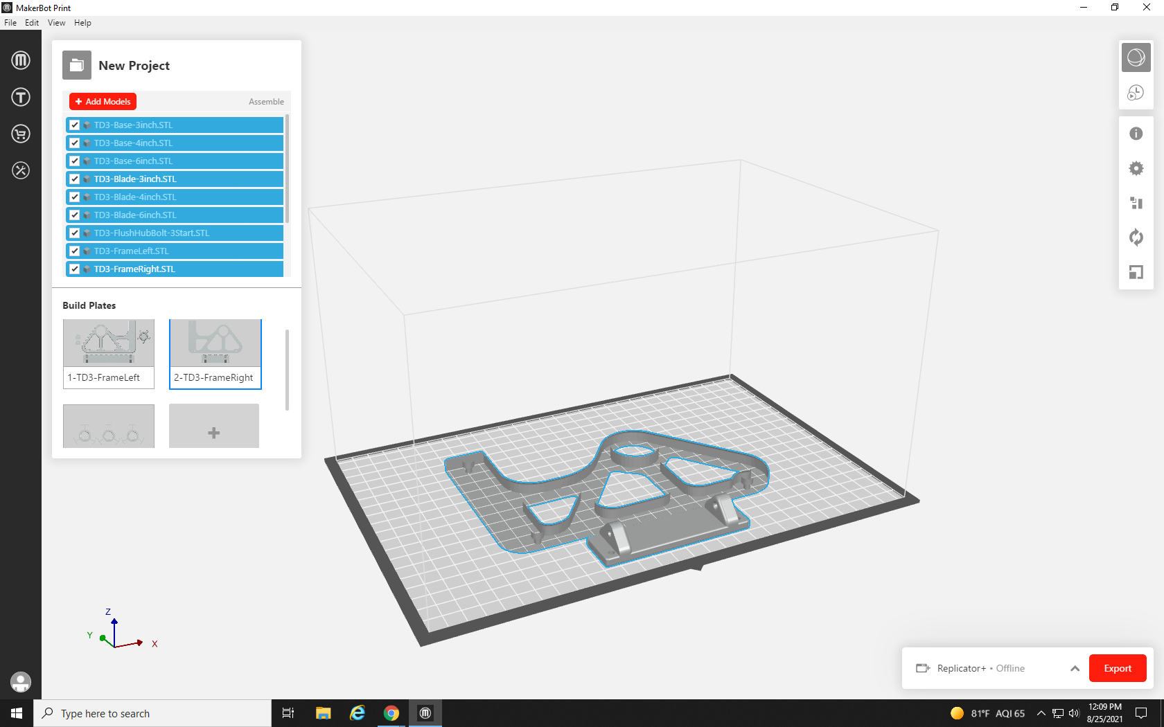
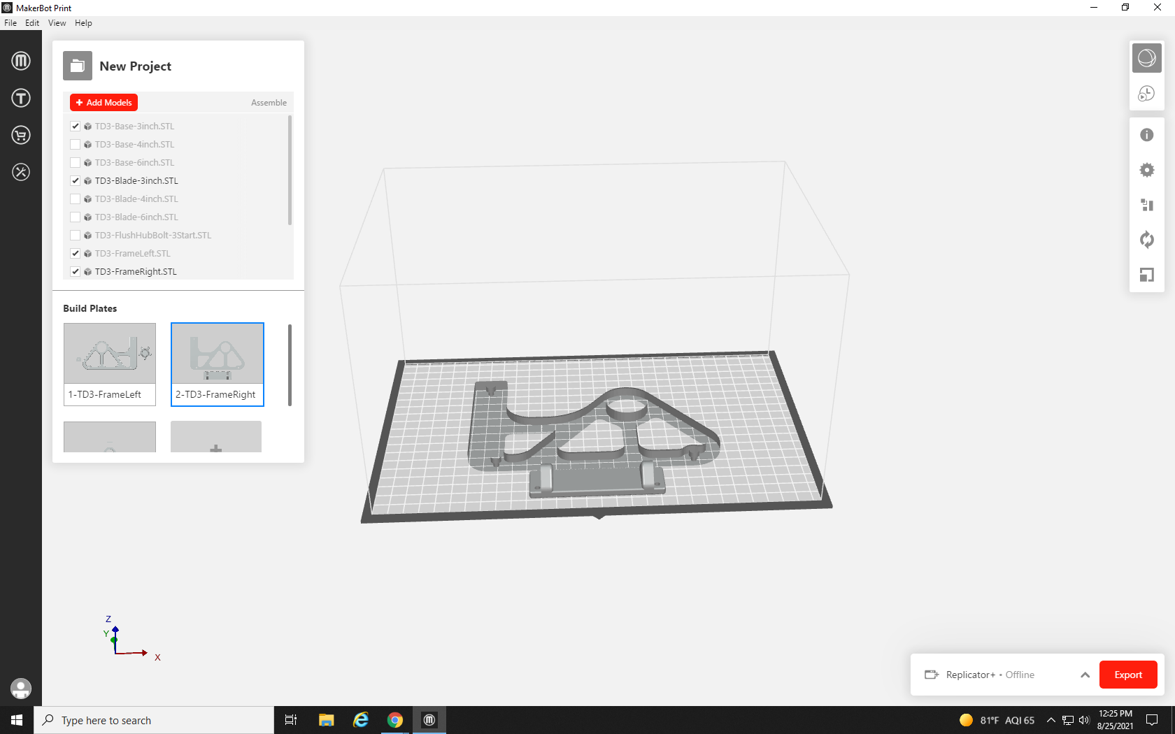
Selecting the second build plate shows what’s on it, which is much less than the first build plate.
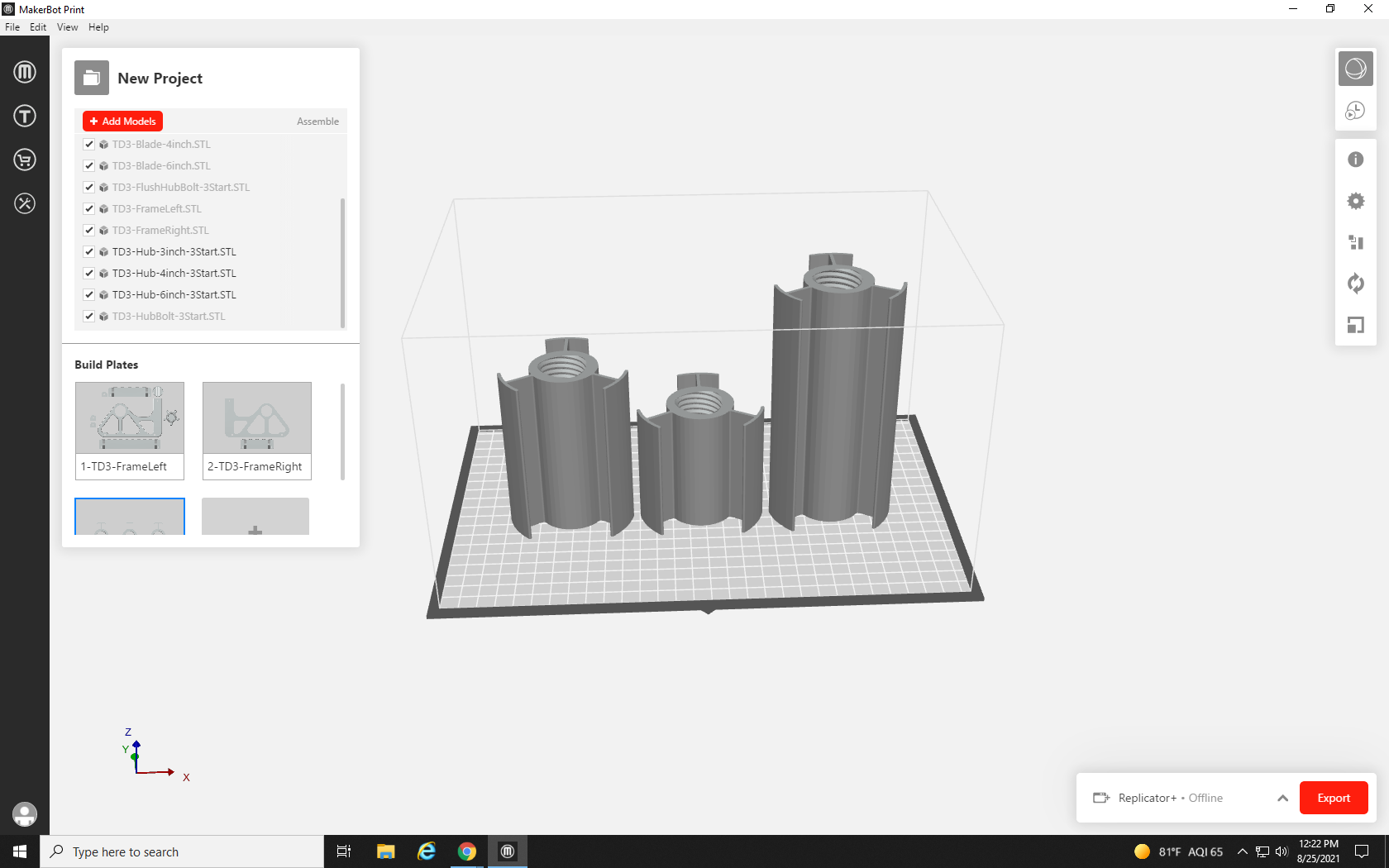
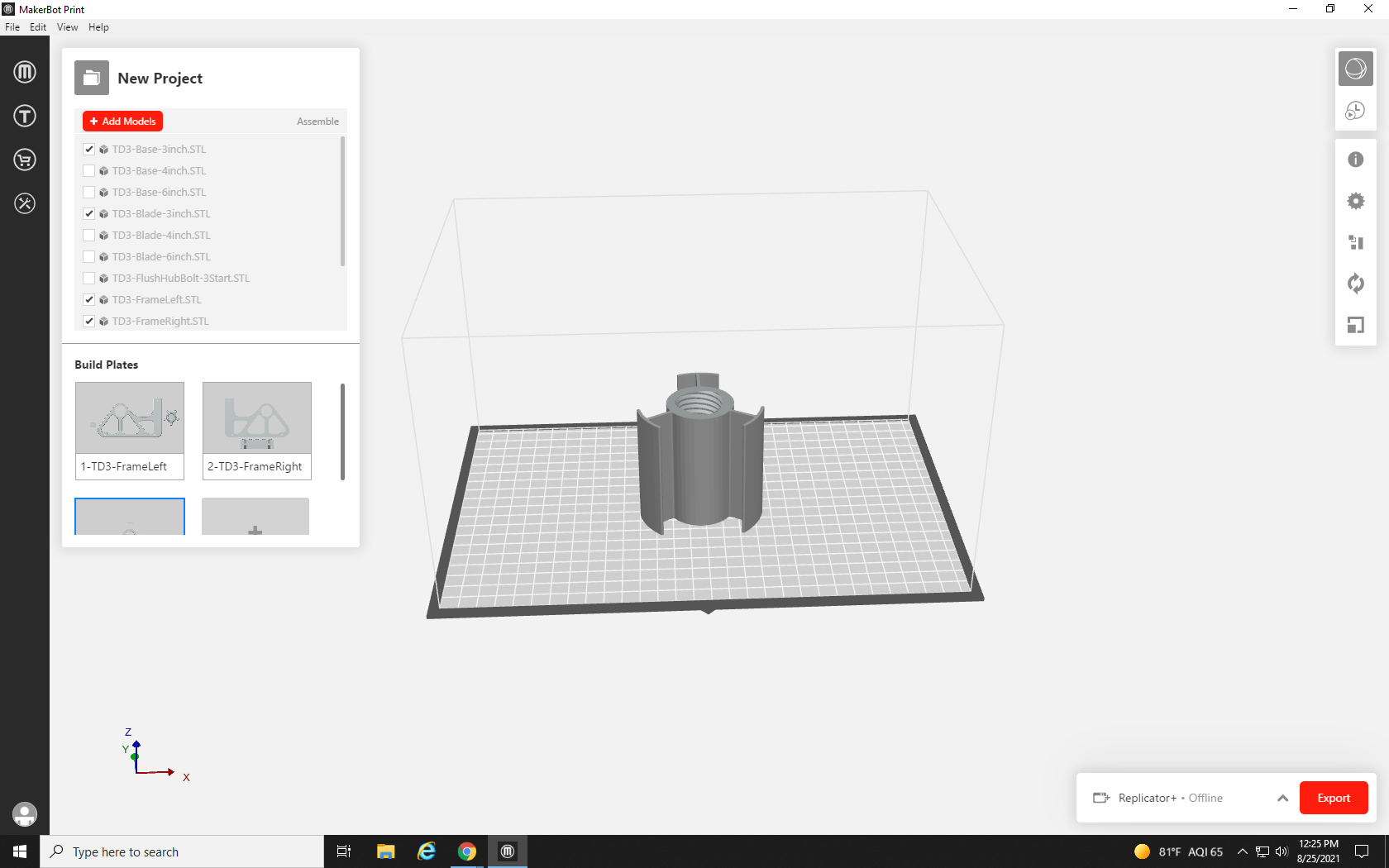
The third Build plate currently contains three versions of the same part: a three-inch roller, a four-inch roller, and a five-inch roller.
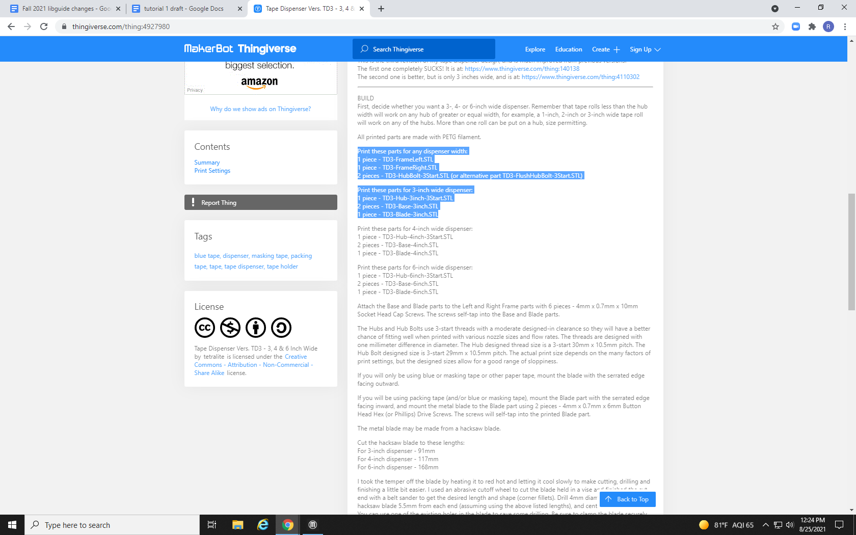
Going back to the description of the print in Thingiverse can provide more information about what parts we need, what parts we don’t need, and what non-3D printed parts, such as small metal screws, we will need to supply to complete the project.
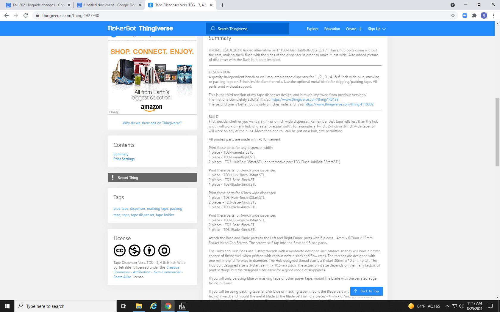
As we can see from the description of our tape dispenser, we will need:
1 TD3-FrameLeft.STL
1 TD3-FrameRight.STL
2 TD3-HubBolt-3Start.STL
1 TD3-Hub-3inch-3Start.STL
2 TD3-Base-3inch.STL
1 TD3-Blade-3inch.STL
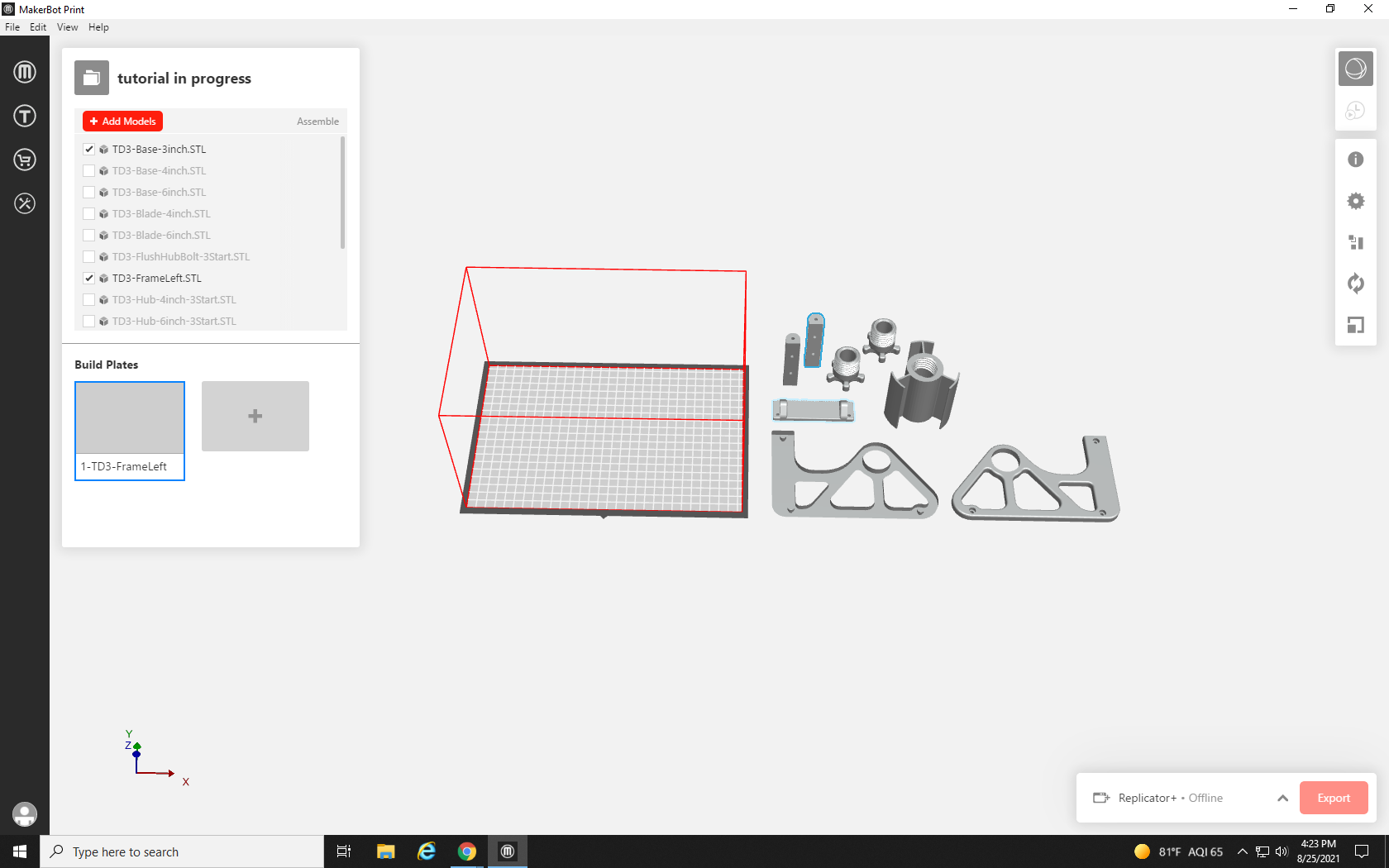
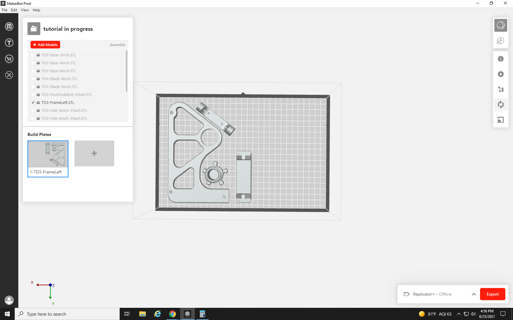
The first step will be to remove any parts we don’t need. To do this, we could identify each part, click on it to highlight it, and hit delete, but there is another quicker and less permanent way. By unchecking the check mark next to each part that we don’t need, it will be as though they don’t exist, but we can bring them back by rechecking the box without needing to reload the part’s file. That cleared up quite a bit of space on Build Plate 1!
Build Plate 2, on the other hand, is unchanged.
Build Plate 3 only has one part – we could probably submit this as three print requests, but with a bit of creative repositioning, we might be able to fit it all onto one build plate.
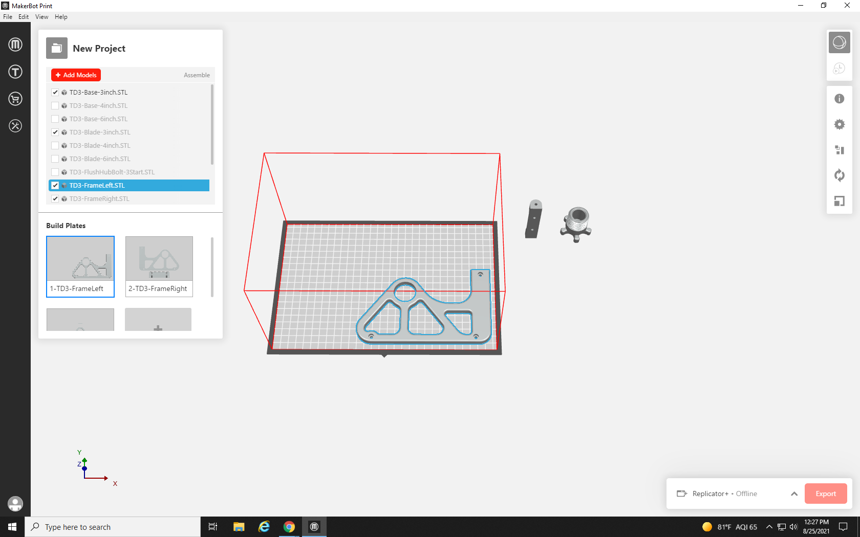
We can now get a clean start on our first build plate, as the big frame portion takes up a lot of space.
We start by clicking on our two smaller parts, and dragging them off the build plate one at a time. As soon as a part leaves the bounds of the build area, the wireframe will turn red to indicate that part of the model is outside of the printer’s range. We also drag our large part to the bottom right corner.
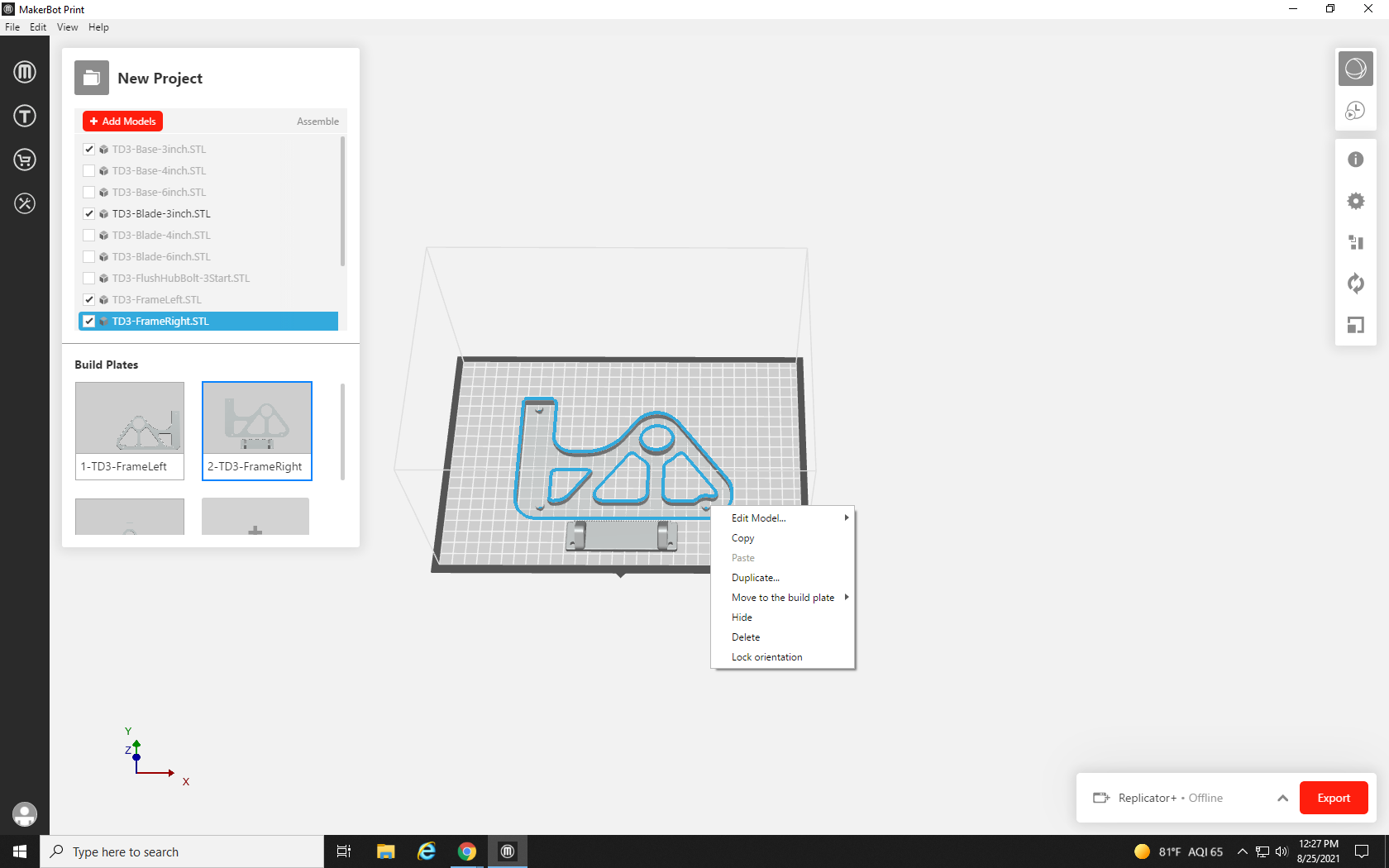
Now, we need to bring the parts from the other build plates over to the first. To do this, right-click on the large part that’s all by itself on Build Plate 2. From the pop-up menu, select Copy (you can also click the part to highlight it and press Ctrl+C to copy it).
Navigate back to Build Plate 1, right-click anywhere in the open build space, and select Paste from the pop-up menu (or click once in the build area and press Ctrl + V on your keyboard).
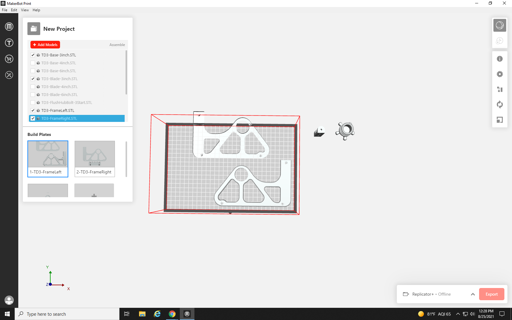
A copy of the part is now on Build Plate 1. It doesn’t look like it fits very well, but let’s drag both large frame portions out of the build plate with our other print parts, return to Build Plate 2, highlight the part you just copied, and hit Delete to remove it from the build plate. Repeat the last two steps with the remaining parts so that they are all on one screen.
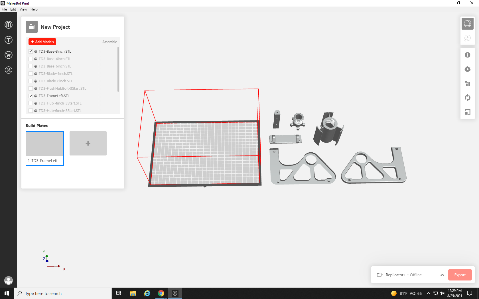
And here we have the pieces all laid out next to a single build plate. When additional build plates are empty, they are automatically removed from the project. But this doesn’t quite look like all the parts that our tape dispenser will need.
Looking back at the summary of the model from Thingiverse, we are reminded that we need two copies of a few of the parts.

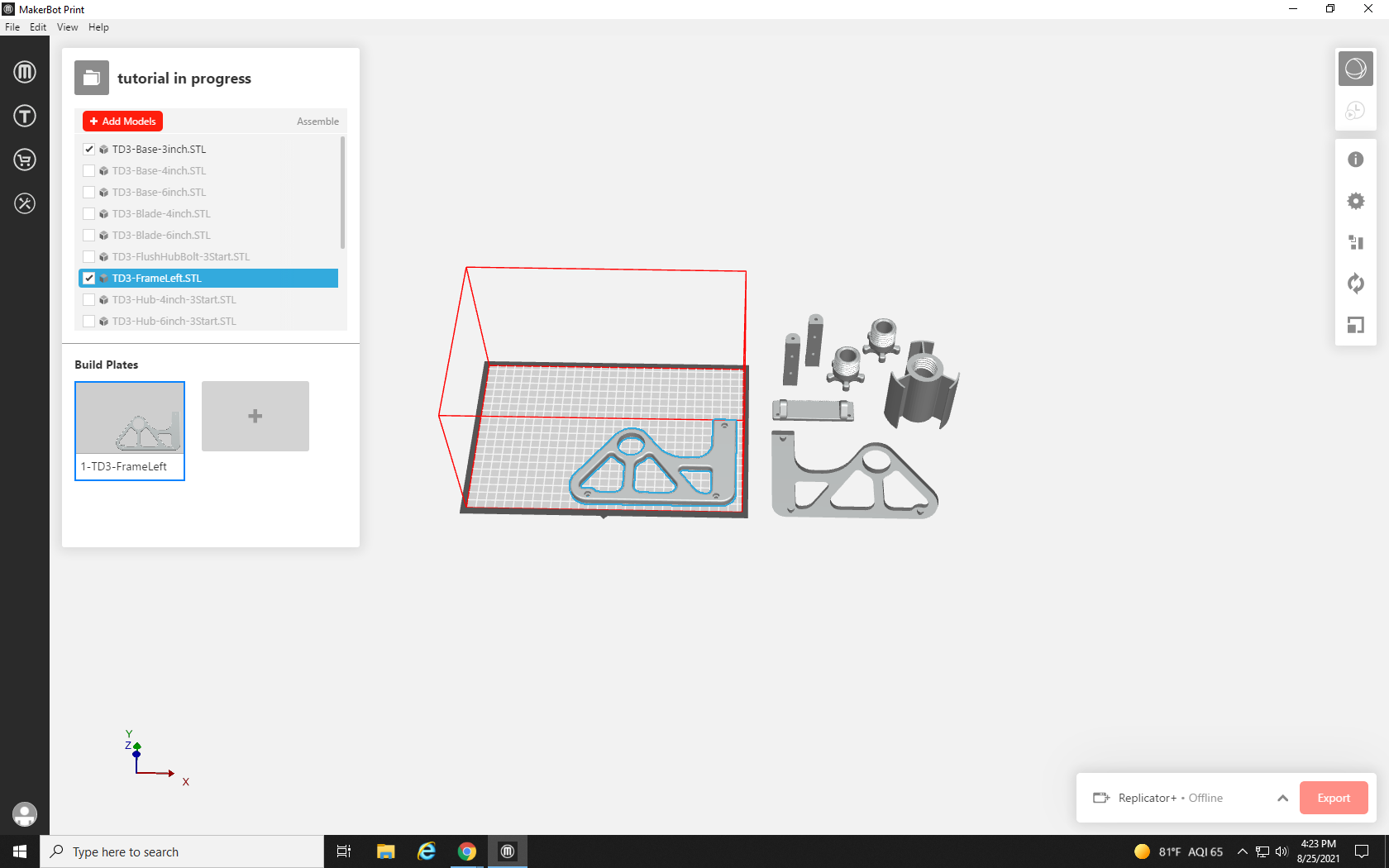
If you aren’t sure which parts have which names, you can uncheck one of the file names you need two of, to make the part disappear and then turn it back on. Once you have identified the parts that need to be doubled, copy and paste a second version onto the screen.
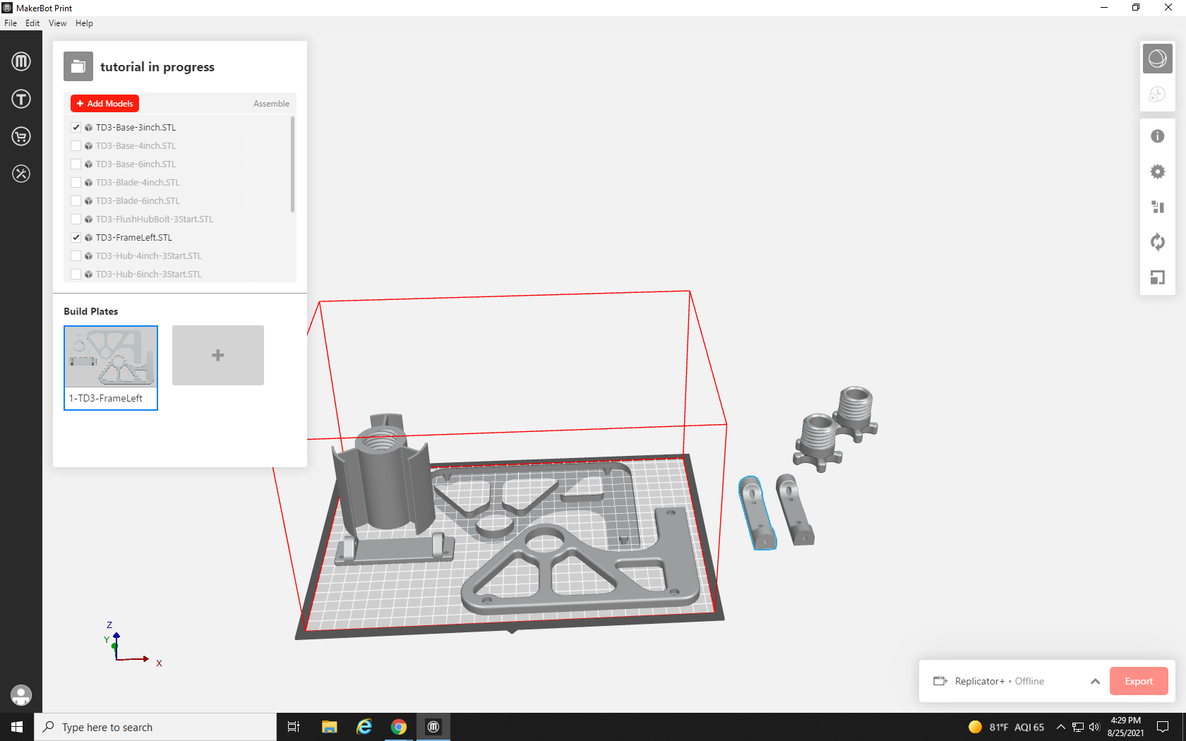
Now with all of our parts on one screen, we can start to organize them. We’ll start with the largest parts and work the smaller ones into place. First, we drag and drop one of the large side frame parts into the bottom right of the build plate.
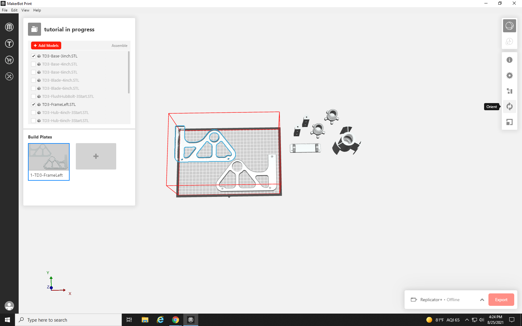
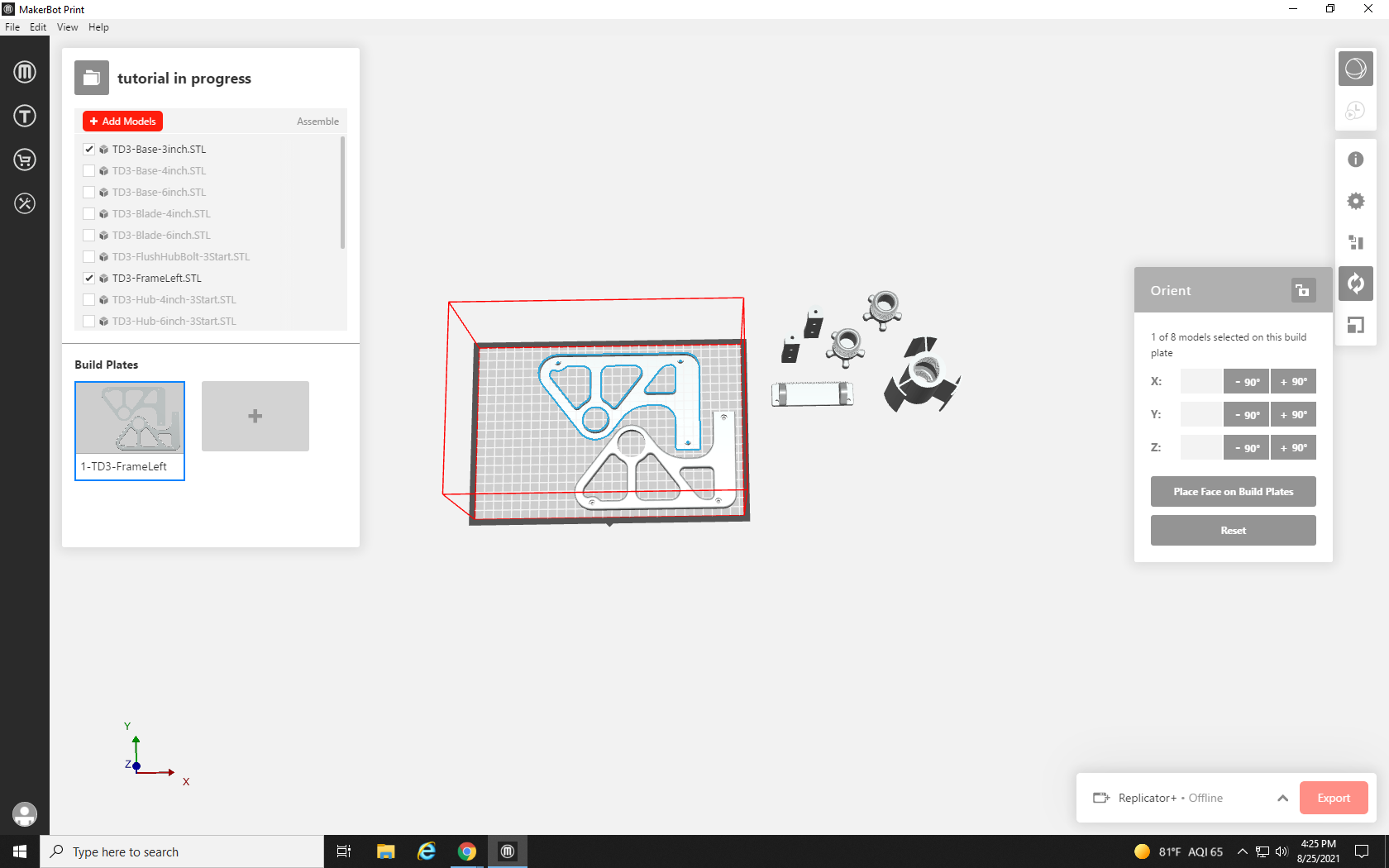
We drag the second part of the frame to the top left, but it doesn’t look like it will fit, but if we turn it around it might be able to. let’s try!
First, we click on our part to highlight it, and then we click on the icon in the right-hand toolbar that looks like a circle formed from two arrows: the Orient tool.
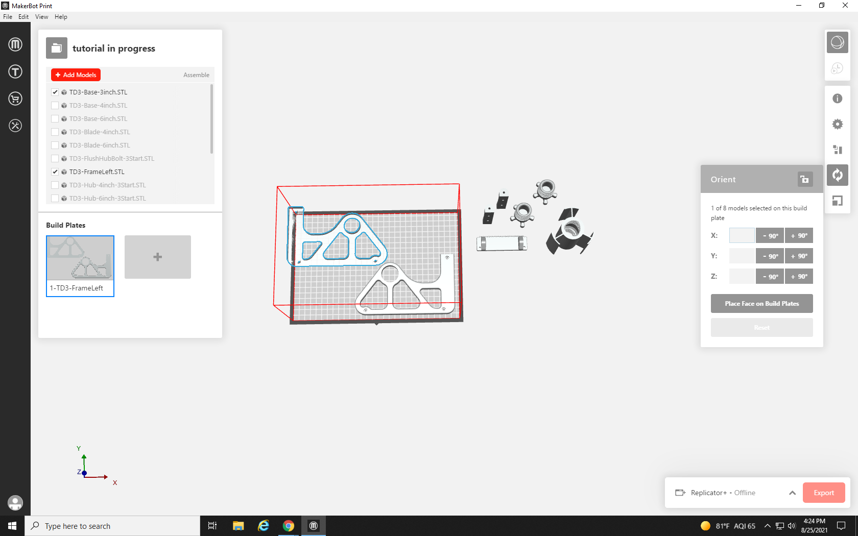
The Orient tool brings up a small box. The majority of the box is filled with three text entry boxes, and below them are six buttons that can add and subtract 90° on three different axes, X, Y, and Z. These axes correspond to the three arrows you see in the bottom left corner, and represent the axes of physical space.
Imagine each arrow as a spear going through the center of the highlighted part. From our angle, looking down on the build plate, the X-axis would go through the part from left to right, the Y-axis would pierce the part from the bottom of the screen to the top of the screen, and the Z-axis would go through the bottom of the part, and straight out your computer screen. Rotating on an axis is like spinning one of those spears; a positive rotation is clockwise, and a negative is counterclockwise. So if we were to rotate the part 90° on the Z-axis, it would be like grabbing the rod that is going straight through the part, and turning it to the right until the side of the part on the left side of the screen runs parallel to the top of the screen.
For the part we need to rearrange, we want to try rotating it 180° on the Z-axis, and we will click the +90° button in the Z row twice.
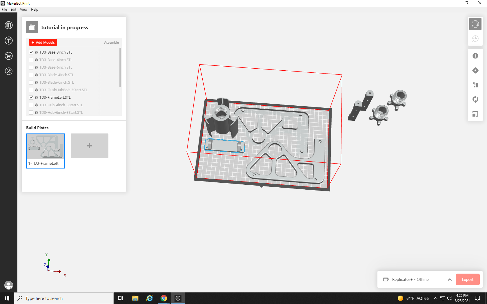
And with our large part flipped around, and the two largest parts placed, we can make more room for our other parts.
We drag in the tall tape holder portion next, and then the tape cutter.
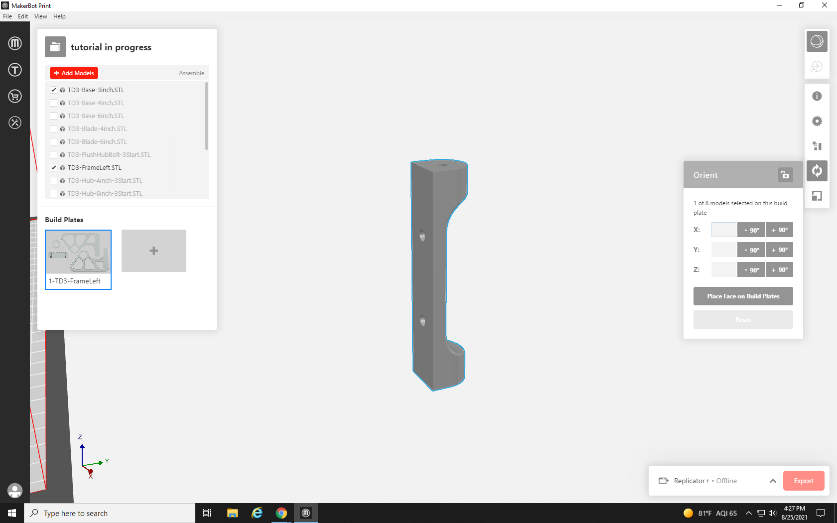
This next part may have problems with its current position. The overhang at the top of the part, where material exists without support underneath it, could cause problems. The slope on this one is pretty small, and the printer could likely do it, but it’s better to be safe than sorry.
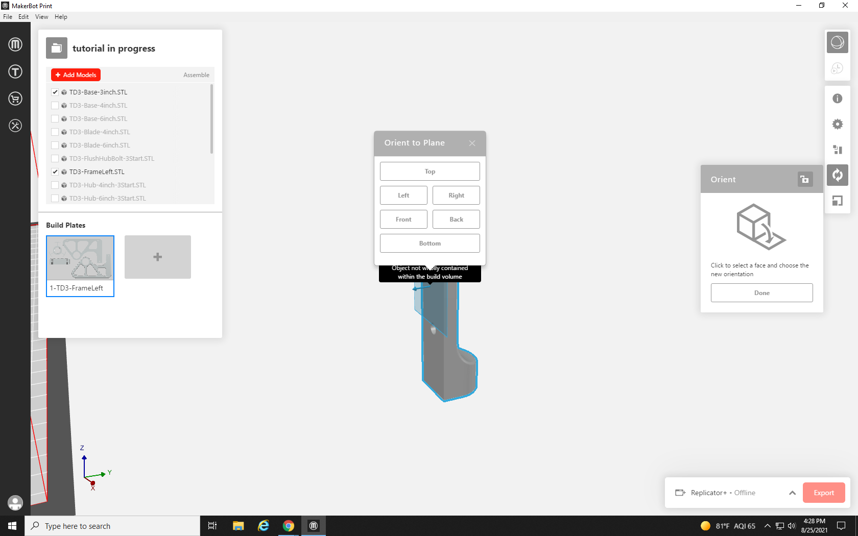
We could use supports, additional breakaway material that the printer lays down to support overhangs, but those use extra material and are difficult to remove from small holes like the ones in the back of this part, so we will lay this part flat on its back instead. Click the part, and then click the Orient Tool. This time, rather than use an axis to rotate, we will use the “Place Face on the Build Plate” button below the box for the Z-axis.
Pressing this button will create a flat plane on whatever face of the part you highlight. Click on the flat back of the part.
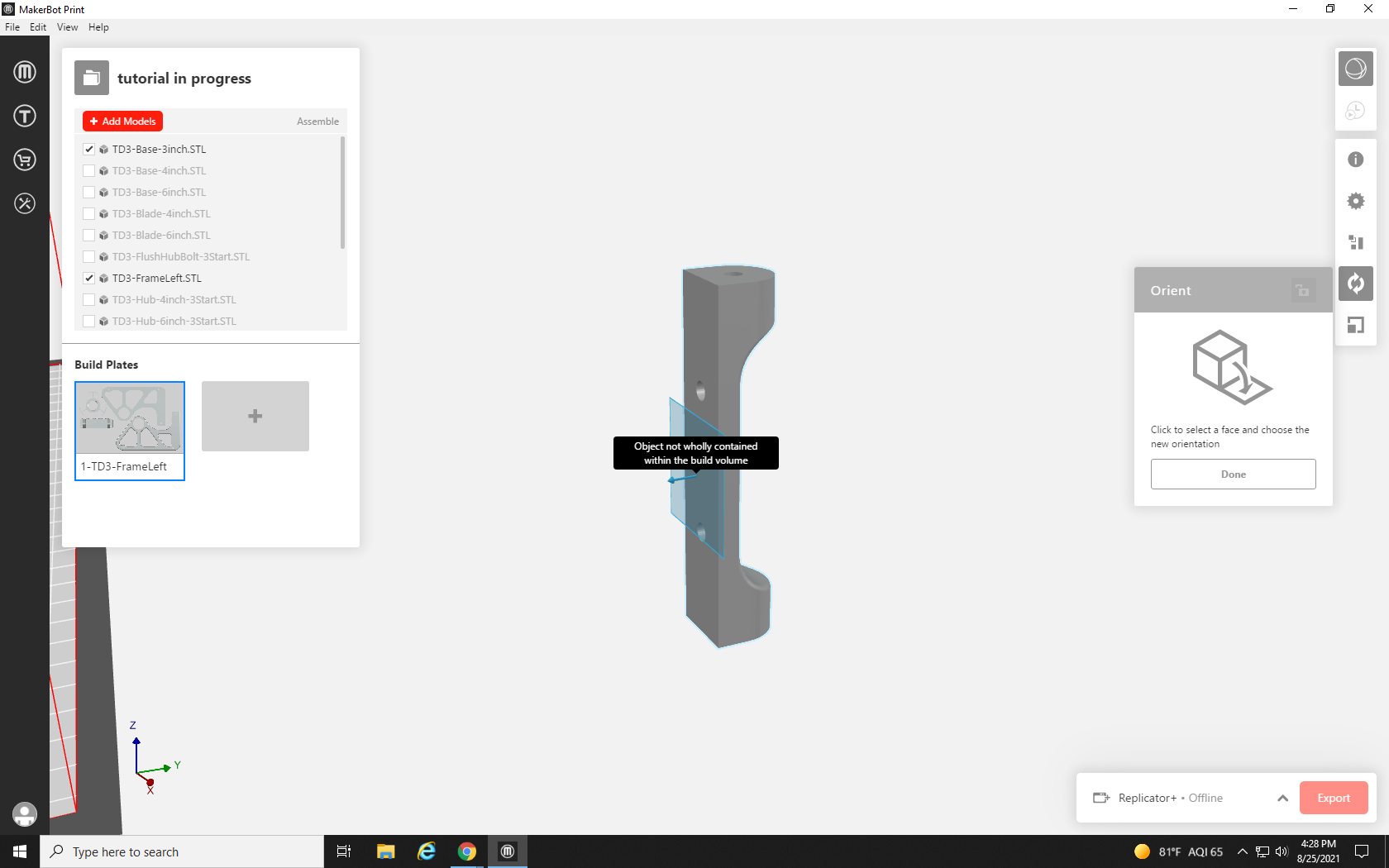
Next, a pop-up menu will ask you what direction you want that plane to face – for this project, select Bottom.
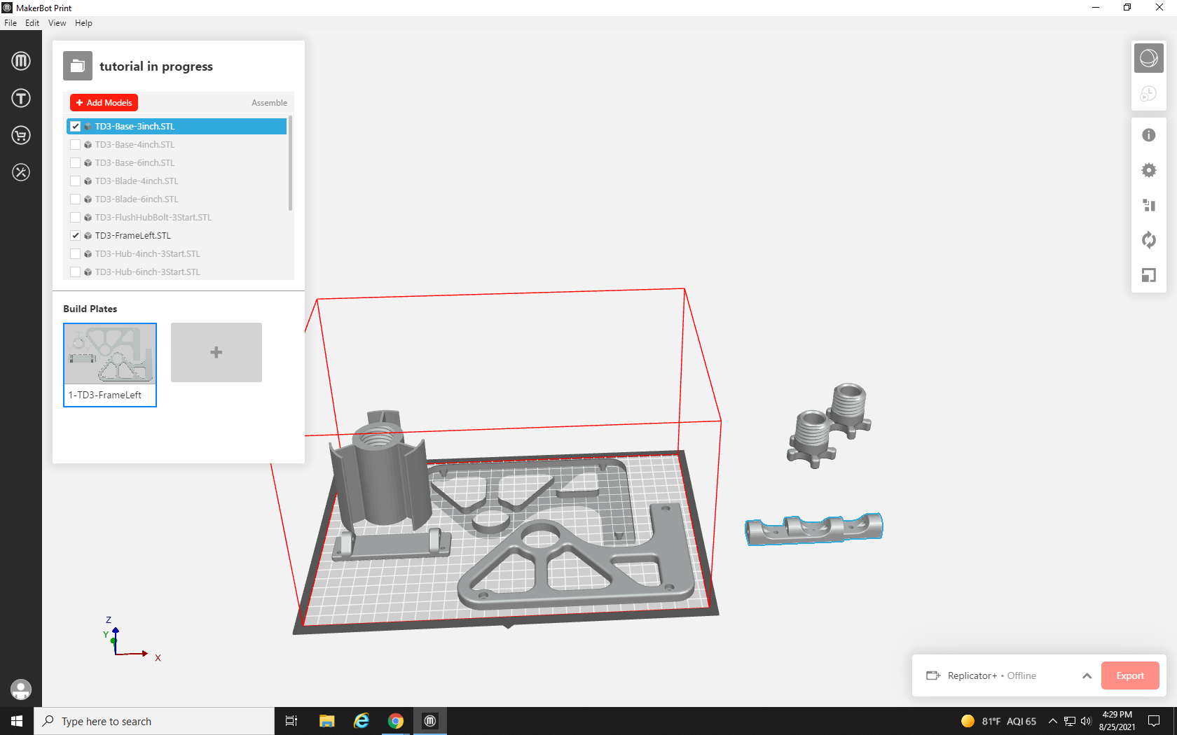
That face of the part will become its bottom plane, repeating the process with its duplicate.
Now, both parts are flat, but they would fit better running parallel to the tape cutter part, so we need to rotate 90° in either direction on the Z axis. Rather than rotate each part individually, we can rotate both at once. Click one part, hold shift on the keyboard, and click its twin. Both parts should now be highlighted in blue. Click the Orient Tool and then +90° in the Z-axis row.
They both rotated, but are now overlapping. Click anywhere on the screen to unselect the parts, and then select each one individually to drag onto the build plate.
With those in place, we just have to find room for the two knobs — and I think I see some space.
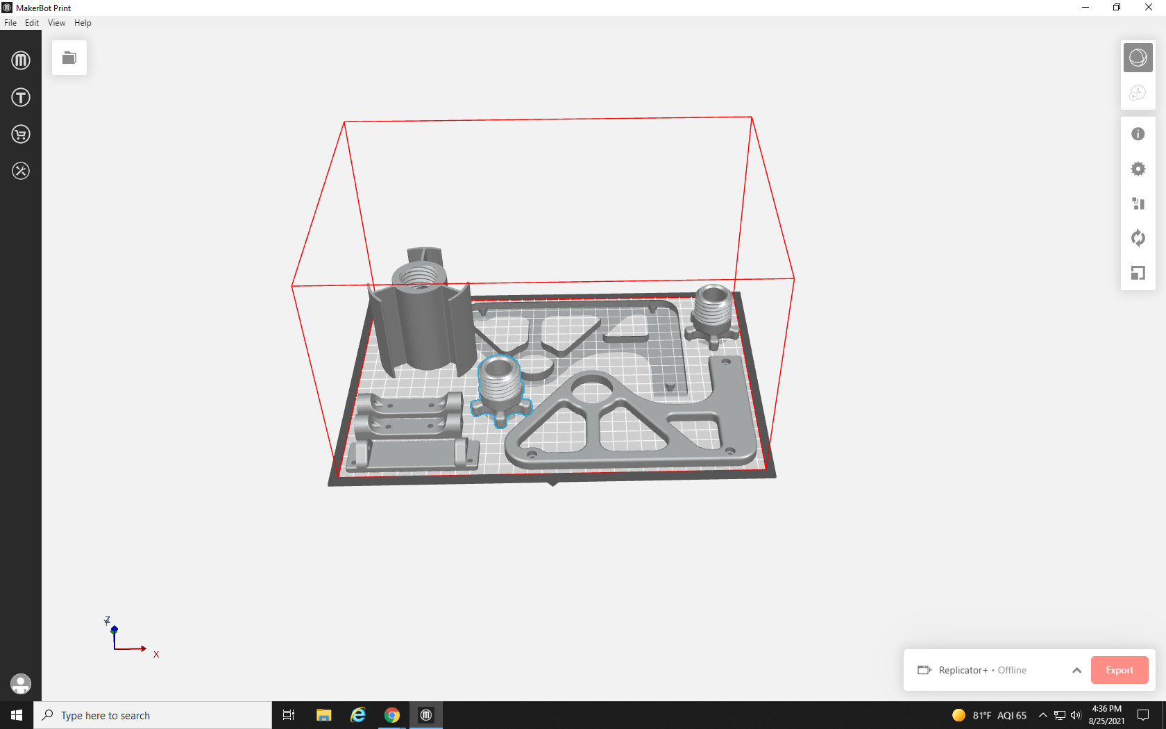
After shifting things around for a final time, it looks like they are all on a single build plate, but something is wrong: the wireframe is still red and the button to slice the print is grayed out!
Even from a top-down perspective, it looks like it fits, so what gives?
Although this looks like it fits, it doesn’t account for a nonvisualized part of the print: the raft. The prints’ raft is a small pad that is 3D printed before the model to give it something to adhere to, but will (usually) easily peel away from the print when it is completed. The raft extends about one centimeter past the edges of the print model and although it’s not being rendered visually, it would be hanging off the edge of the print bed, leaving us with a wireframe error. Let’s try a different arrangement of parts.
Several hours later…
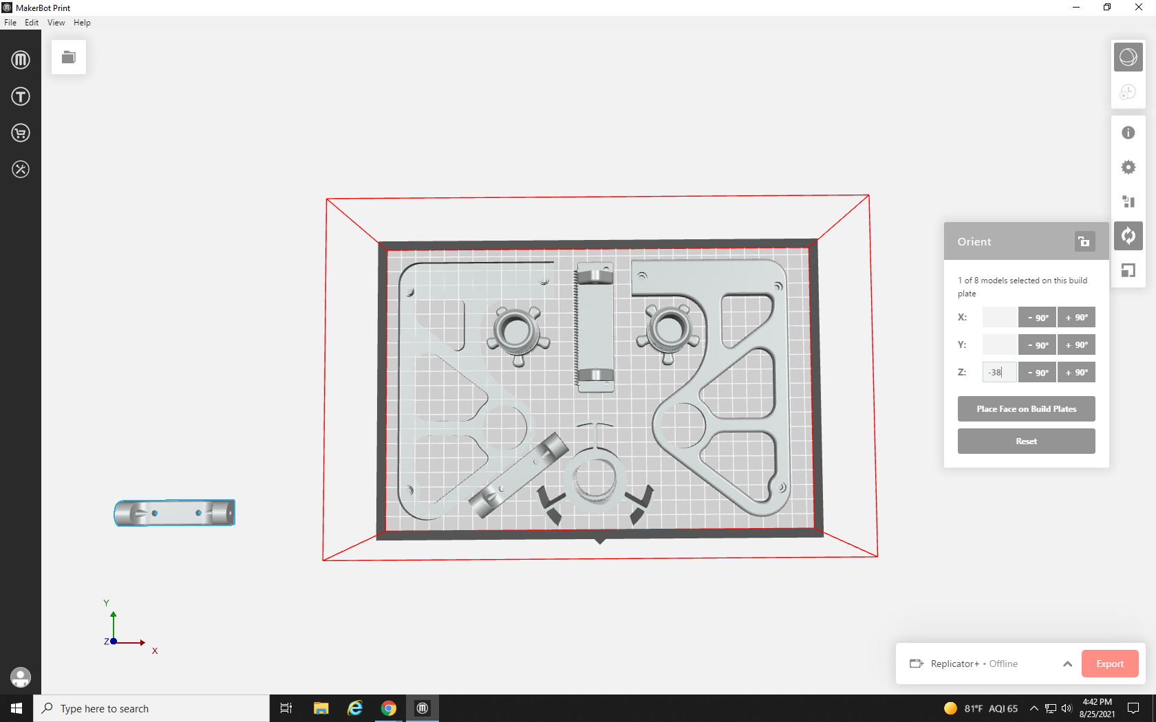
It looks like we have managed to get things a little farther from the edges in this arrangement, and there’s only one part left to place. To finish the build plate, we need to rotate this part on the Z-axis until it is diagonal – a mirror of the other part that I have already rotated.

Because we don’t want to rotate it a full 90°, we will use the text box to input the angle. I already experimented by adding and subtracting measures with its twin until I found the best angle to fit between those parts, 38°. Because we need this one to rotate in the opposite direction we enter -38 in the box that corresponds with the Z axis, and then press Enter, and drag it into position.
As soon as the wireframe turns gray, you know the build plate can be printed.
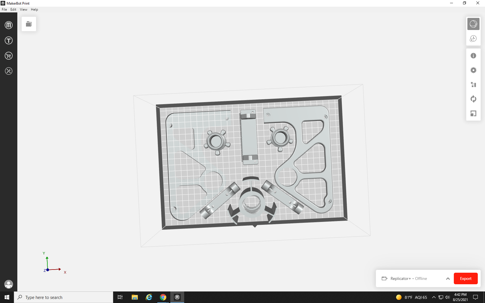
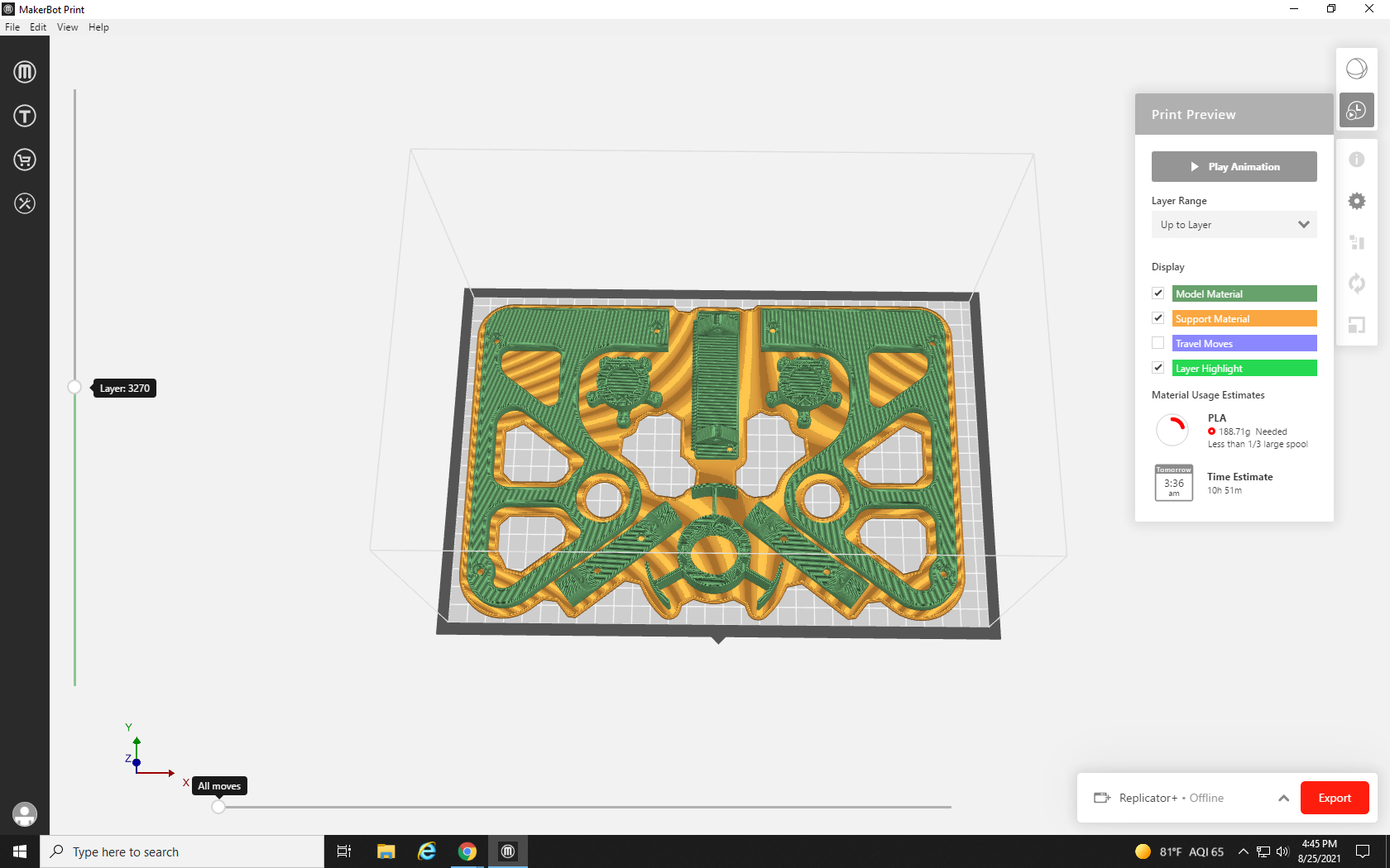
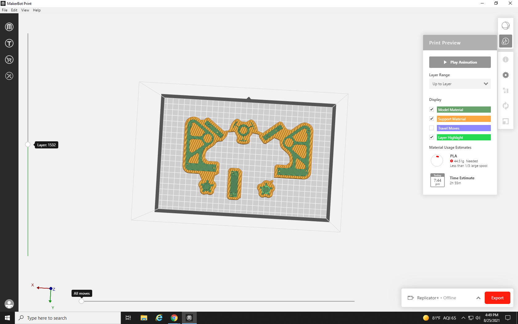
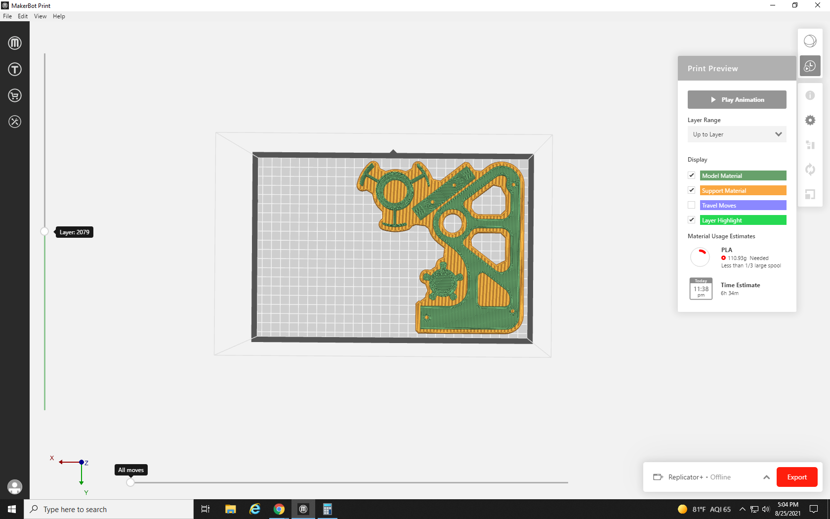
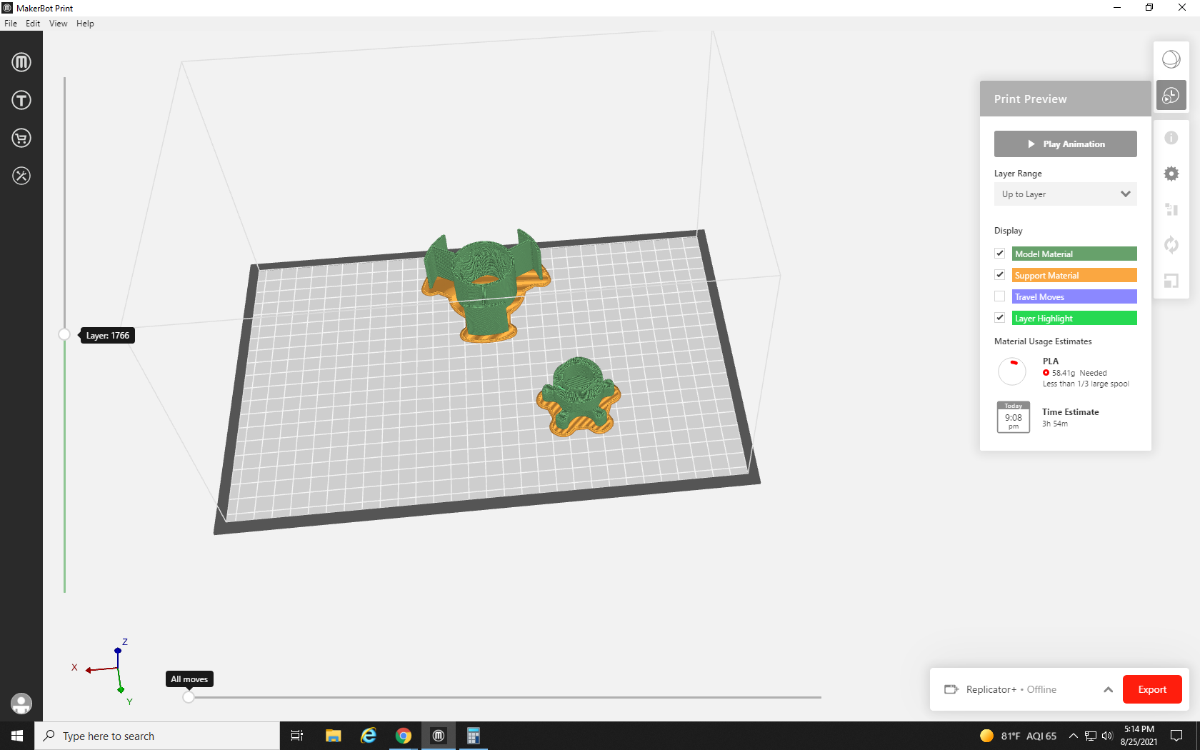
Satisfied with our well-organized build plate, let’s hit the “Print Preview” button at the top right and let the slicer do its thing. When there are more parts to account for on the build plate, or even just large parts, there are many more paths in the printing process that the printer needs to calculate, so it takes a little longer to process.
As the paths render layer by layer, you can see exactly how the printer will create your model. With the default settings, the green portion is the model itself, while the yellow portion is support material; in our case, the raft that prevented us from using our other arrangement. This part can take a while too, so try to be patient.
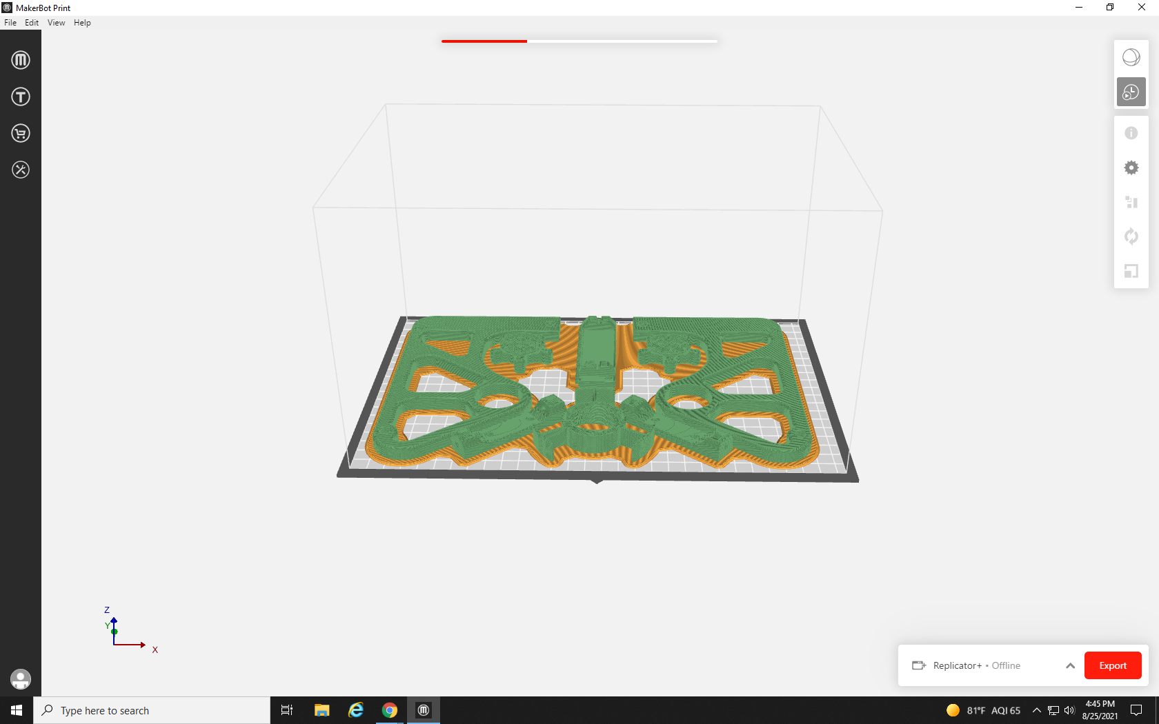
Now that it’s rendered we can see how much material and time it will take to print: 188.71 Grams, and almost 11 hours! Well, I can’t include that in one print request. How many requests will I have to fill out for this tape dispenser? 188.71 grams divided by 80 grams per print = 2.35 requests. We can’t submit 0.35 of a request, so this will have to be three requests.
Of course, if we were printing it at home I could simply click Export and print it in one go, but to ensure that the Re3D program can stay free for all students, faculty, and staff, we must limit the size per request. It may seem strange to place three requests rather than just one when in the end, the amount of material used will be the same, but the usage statistics of Re3D account for large vs. small requests. This helps us better understand how the program is being used, how we can best help our patron community create their projects, and what people would like to get from printing with Re3D.
For prints that aren’t made to fit non-3D printed parts, there is another way – we could make everything smaller using the Scale tool. Let’s see how it works: First, select all of the parts on your build plate by holding shift and clicking on each one. When everything you’ve selected is outlined in blue, click the Scale tool icon located on the bottom of the right-hand toolbar.
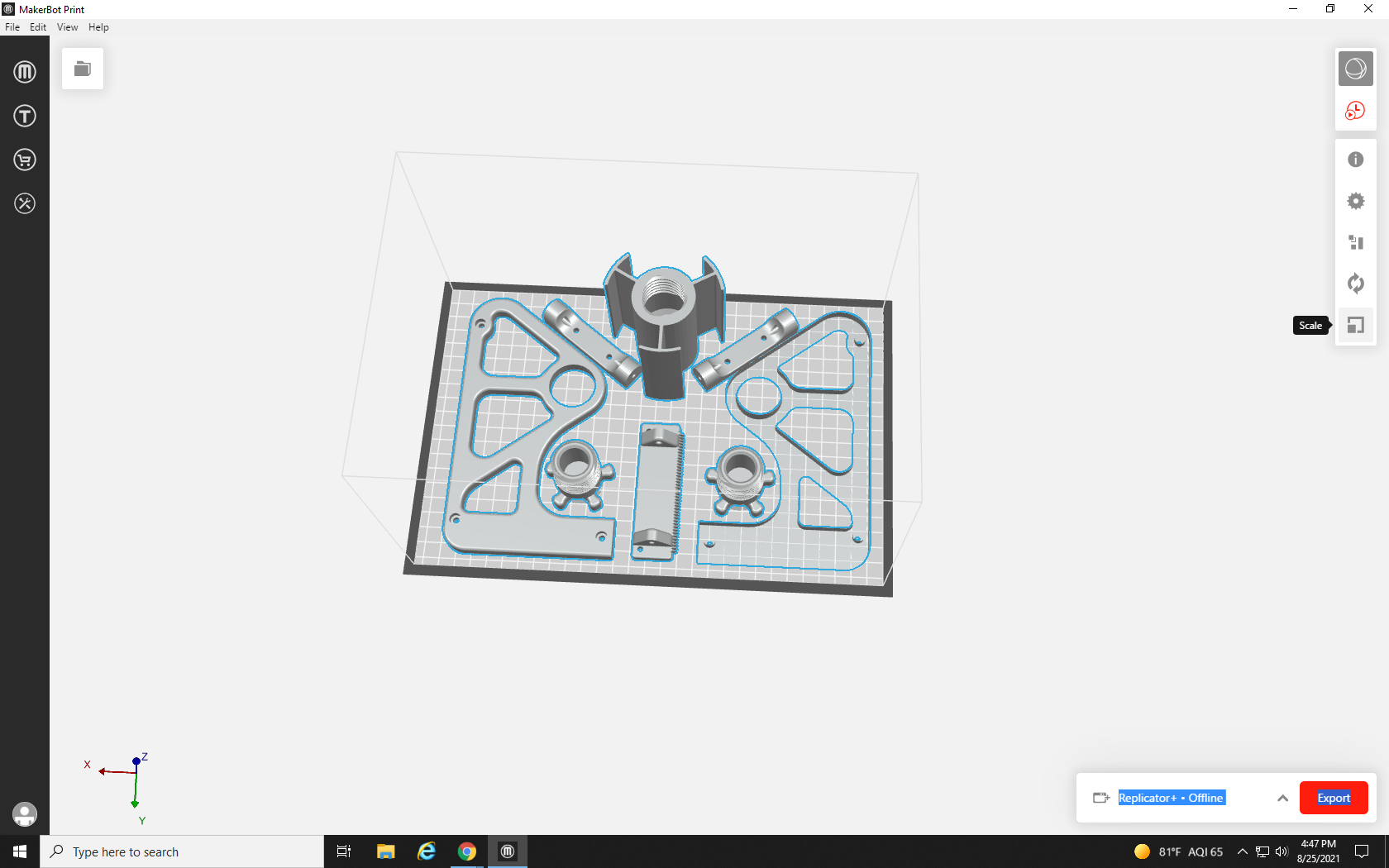
Similar to the Orient tool, you are presented with three text boxes which each represent the scale of the object as a percentage of its original size (currently all set to 100%) along the same axes we learned in the Orient tool. From the current angle of the build plate, changing the X% up or down would stretch or shrink all of the objects horizontally, Y% would stretch or shrink them vertically, and Z% would make them taller or shorter. Of course, adjusting just one of these axes would distort the shape of the objects, and is rarely something you want to do, so it’s best to keep the “Uniform Scaling” checkbox checked. This locks the axes in proportion to each other so that scaling one axis scales all three axes simultaneously.
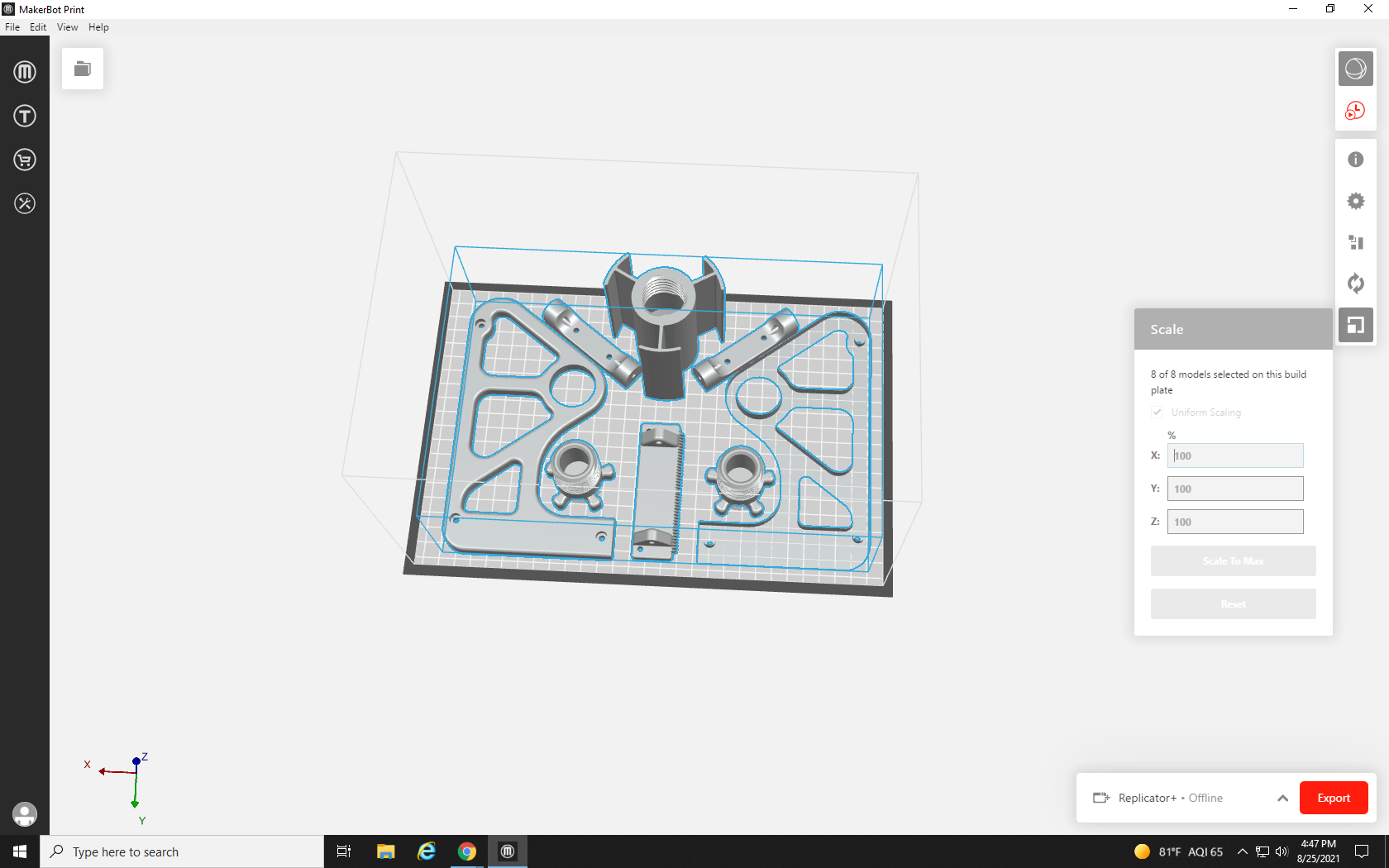
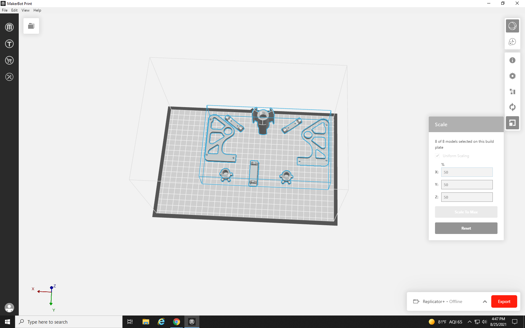
If you select and scale a single object, rather than a group, you will encounter six text boxes rather than three. The additional text boxes let you scale the object by its actual measurement (in millimeters or inches for example) rather than just %. We want to shrink the whole project, so with Uniform Scaling enabled, we change one of the 100% field entries to 50% and hit Enter on the keyboard.

This has made all the parts smaller but kept their proportions. Of course, there is now much more space in their distance apart as well. Let’s see how much material it uses now, by clicking the print preview icon
It takes much less time to process and only uses 44 grams of material. That’s way less than 50% of 188 grams! The material used is NOT directly proportional to the size, many other aspects affect it, and often to reduce the material used by 50% you only need to shrink the print by 10% to 20%. Of course, if we printed at this size, the tape dispenser wouldn’t fit our tape or the screws we will need to use to assemble it, so let’s get big again. Hold Ctrl on the keyboard and press Z to undo your most recent actions.
After arranging the parts so well, it feels like a shame to split it back up onto different plates, so we won’t. Let’s go to the project menu where we can see all of the parts in our build, and uncheck some to remove them until we think we have a manageable plate.
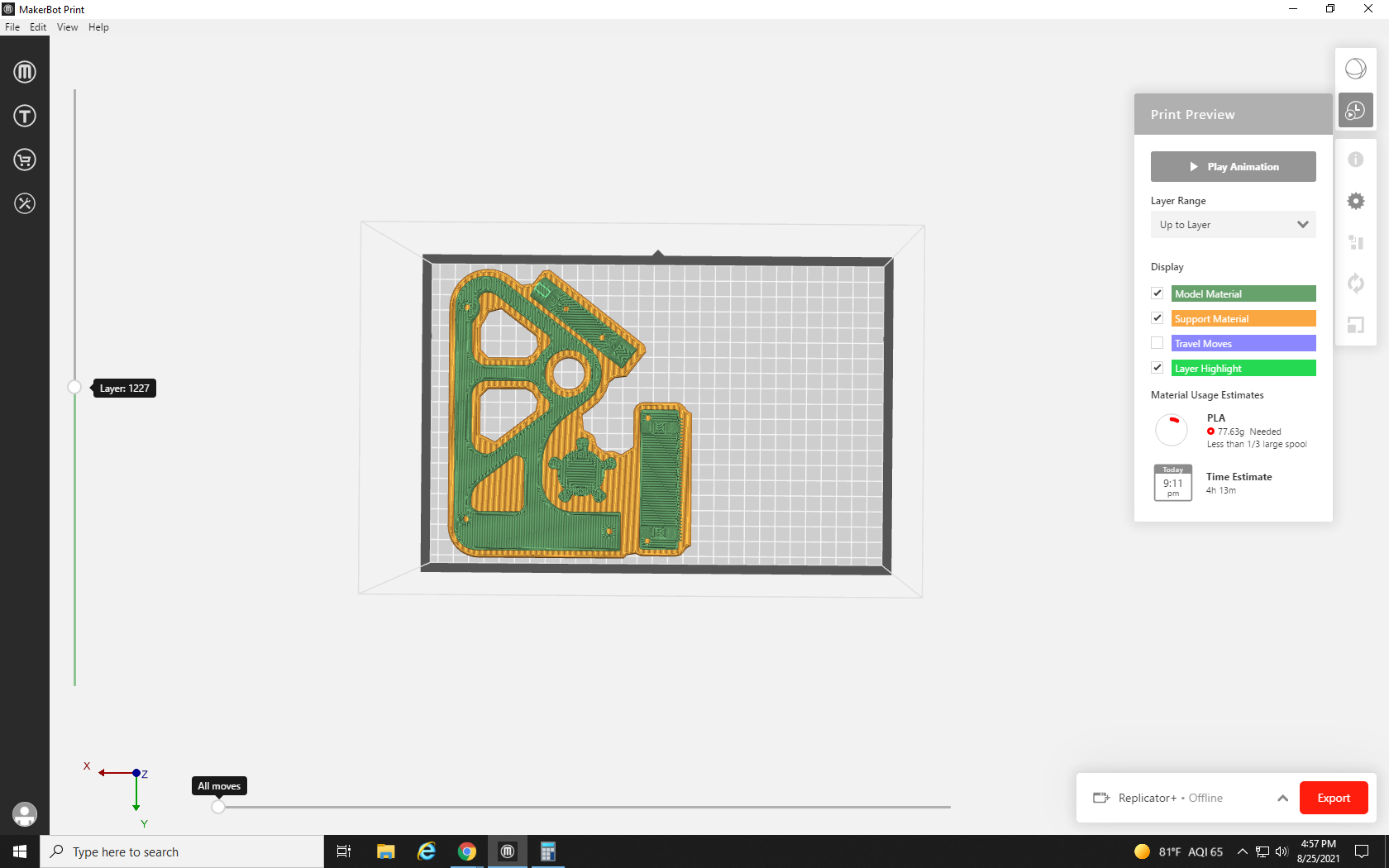
With a little more than half the parts gone, I think we should be good, let’s test it by hitting print preview once again.
77.63 grams! Nice, we are under the request limit so let’s get these parts exported.
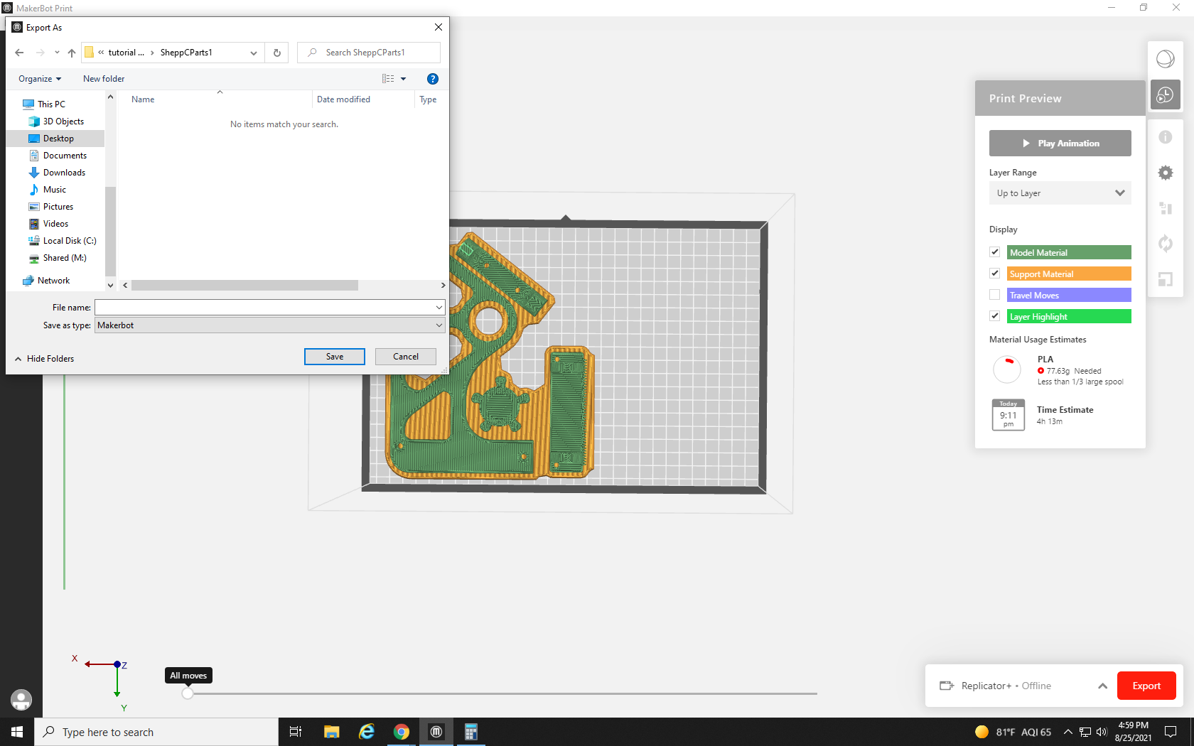
First, to make the parts easy to see and approve, we’ll export our project as a .stl file. Click the File menu in the top left of the screen, and then select Export as…
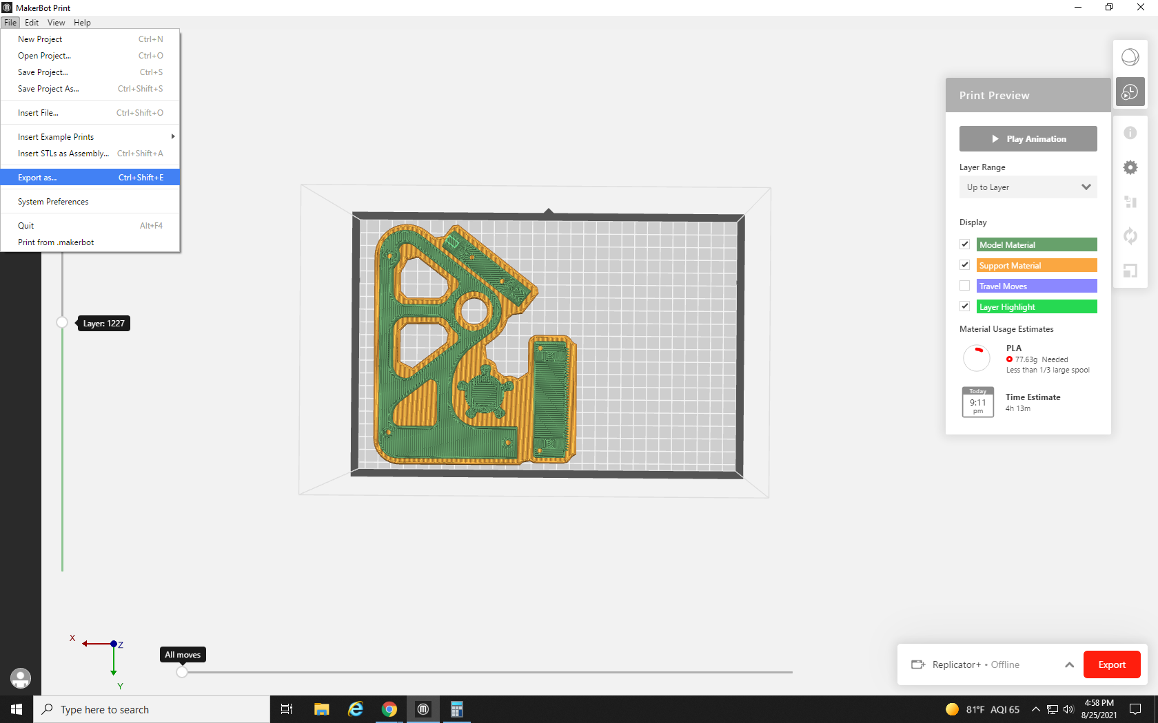
Make sure you save your files in a place you can remember, like a new file on your desktop, and name it something descriptive like the “Tape Dispenser Side” followed by the number 1 and the file suffix “.stl” —
— ideally, you will see a popup at the top of the screen telling you your export was successful.

Now we save the MakerBot file by selecting the File menu in the top left corner and then selecting Save as… You should be taken to the same file where you saved your .stl file. Give this file the same name (without the .STL at the end) and hit Save.

With the files ready for our first print request, it’s time to bring the other parts back. What were they called again? No worries, we can just hold the Ctrl key on the keyboard and tap Z.
After a few taps, we are back to our full build plate. Now we can go ahead and turn off the parts we just saved, or if we can’t remember their names, we can click on them to highlight and hit the Delete key. We won’t be needing them anymore
Just in case the decreased raft area is enough, we run the print preview. At 110 grams, it’s still too much, so let’s turn off a few more parts.
This is now only 52 grams, so that works. Save the file in the same location as file 1 with the number 2 after the title, and export it as a .stl file of the same name.
Repeat that process one more time with the final parts, and you are ready to submit your three print files.
With the files all saved in a findable location and with numbers to indicate which print request they will be, follow the instructions covered in Tutorial 3 three times, once for each request. The Re3D Student Printing Supervisor will recognize that the three requests go together, and will process the three requests as one. This means even though you have to put in separate requests, you will only have to pick up a single package that contains all of the printed parts.
Join us in Tutorial 6, where we’ll go through all the print settings available in Makerbot.Print, what they mean, and how we can tweak and adjust them to get the most out of your print.
Additional breakaway material that's laid down by the printer to support overhangs, ledges, and other offshoots from the main body of the print.
