6 Tutorial 6 – Fine Tuning Your Print Setting Options
Fine Tuning Your Print Setting Options
Amanda Shepp and Christopher Shepp
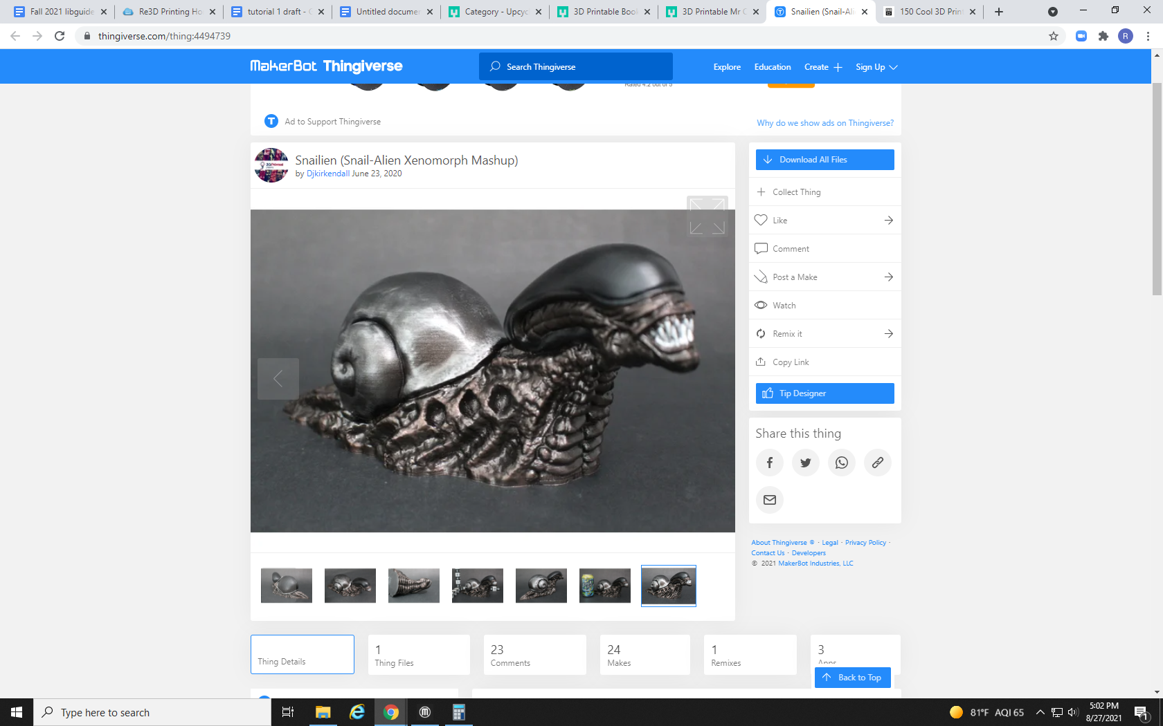
Hello, and welcome to the sixth and final tutorial in our Re3D 3D printing tutorial series. In this tutorial, we will process and scale a more complex print that requires support structures, we will explain the scaling process, each of the settings in MakerBot Print, and how they can be tweaked for an optimal print. For this tutorial, we will be using the “Snailien” garden model available here. Although tutorials 1-5 are not necessary to understand the material, the rest of the tutorials can be found in chapters 1-5.
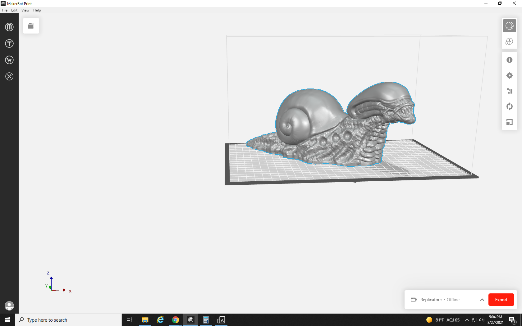
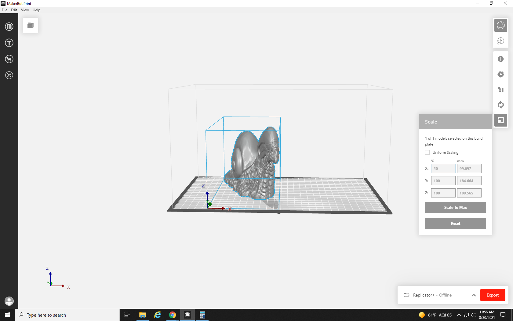
The first thing you may notice upon loading the file into MakerBot Print is that this model is HUGE! It takes up almost the entire build space. Although that would be an awesome garden decoration, there is no way that can be under 90 grams. But let’s see just how long it would take at this size.
If you followed along with us on the past tutorials, you know it can take some time for MakerBot Print to slice and process a file for printing. You may not have noticed until now, though, that not just complexity, but also size, increases the processing time. We may be here for a few minutes.
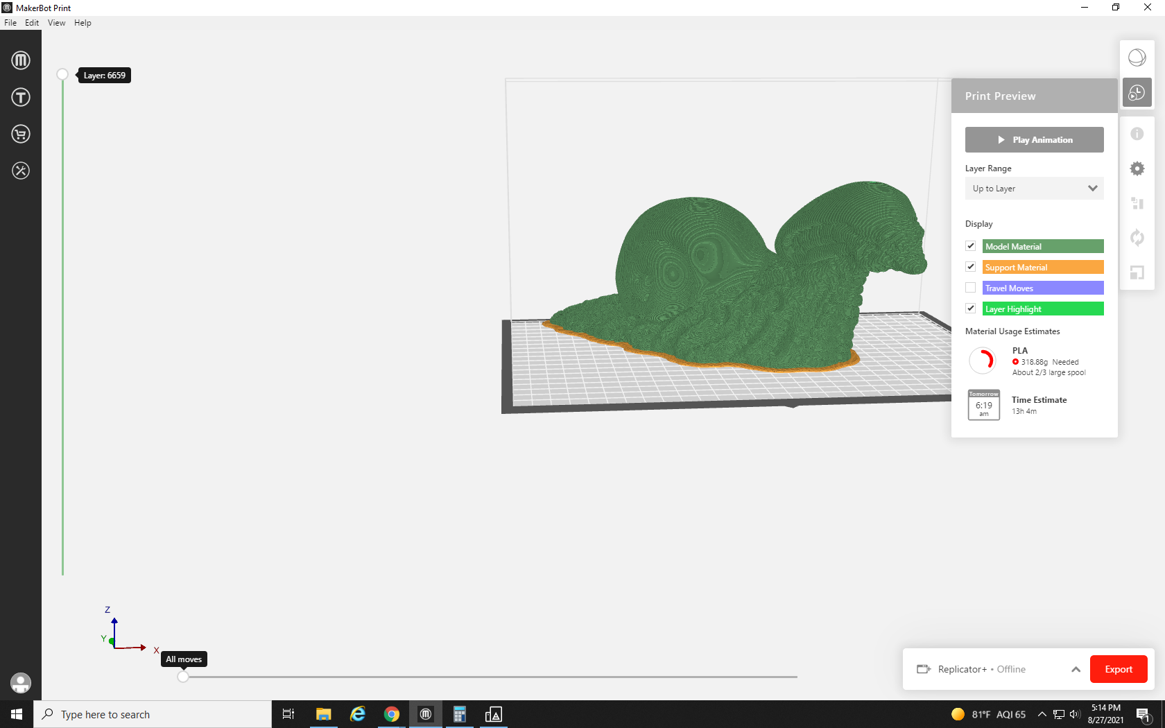
But when it’s done, we can see its estimated material use is 318 grams and will take over 13 hours to print. This could be acceptable on a home printer, but this is way too much for a free print from Re3D. If you would like to order a large-scale print like this from Re3D it is possible, simply email Re3D@fredonia.edu with your request. We will do our best to fulfill it, but for prints larger than 80 grams students must provide their own filament.
I was looking for a smaller desk decoration though, so we are going to scale it down to a more manageable size.
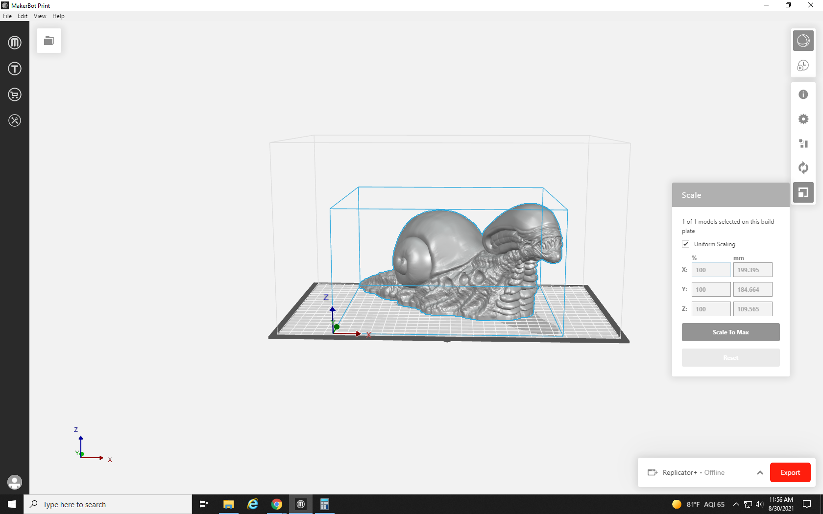
To resize our print we will click the model to highlight it in blue, and then click the scale button at the bottom of the right-hand toolbar.

This will open up the Scaling dialog box. This tool is very similar to the Orientation tool we discussed in Tutorial 5. The three rows of boxes represent the three axes that can be seen at the bottom left of the print. From our current vantage point X runs right to left, Z runs up and down, and Y runs forward and back. Each axis has two text boxes: the first represents the scale as a % of its original size, so right now all three are set to 100%. To the right of those are boxes that display the size of the print along its corresponding axis in mm. There is also a button to scale the model to the largest size that will fit in the build space in a single click. Finally, towards the top is a check box labeled “uniform scaling.”
We recommend always leaving uniform scaling on, as it locks the proportions of the three axes. If you were to uncheck it and adjust only one of the axes, the design then becomes squashed and skewed.
But If the box is checked, reducing any axis to say 50%, automatically adjusts the rest to maintain the design’s proportions.
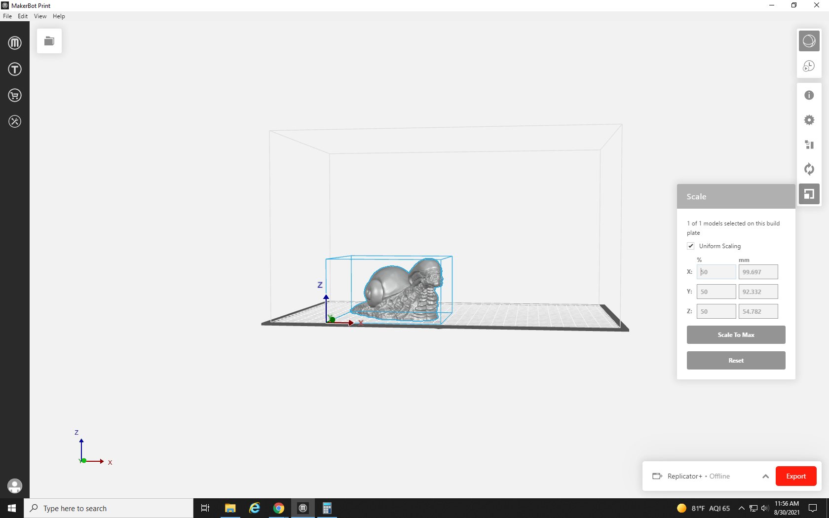
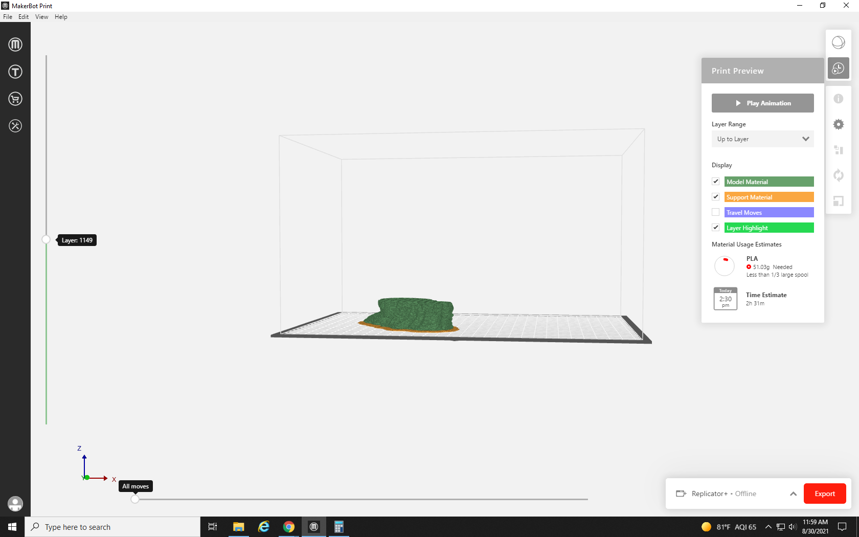
After reducing our size to 50% we see that the print now only requires 51 grams and will complete in roughly two hours. Now that is a print we can request for free! But there are still some things that will need to be adjusted. Due to the way the snailien’s head protrudes forward with nothing below it, support structures will be needed. This is also a very detailed print, so let’s see what we can do in the options to get the best results possible.
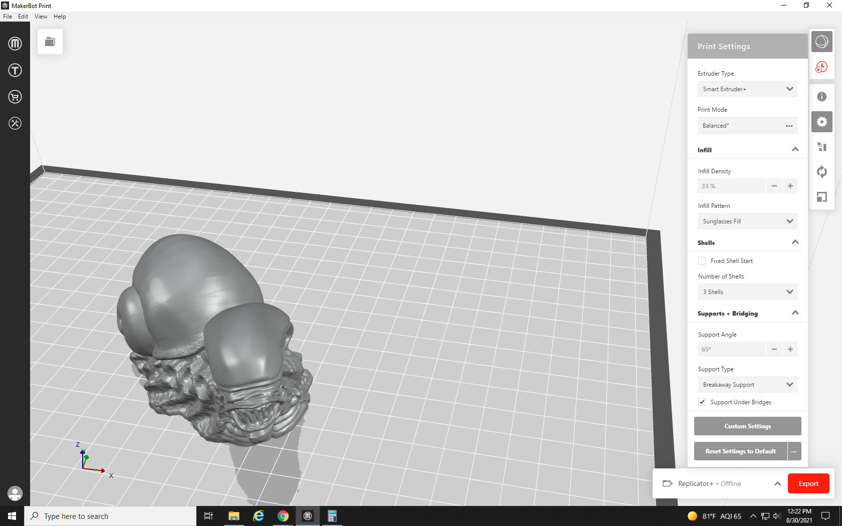
When we first click the gear in the right-hand toolbar, it shows us some of the settings we have changed for recent prints, but we want to take full control of the quality of this print, so we will click “Custom Settings” to look through all the options available to us.
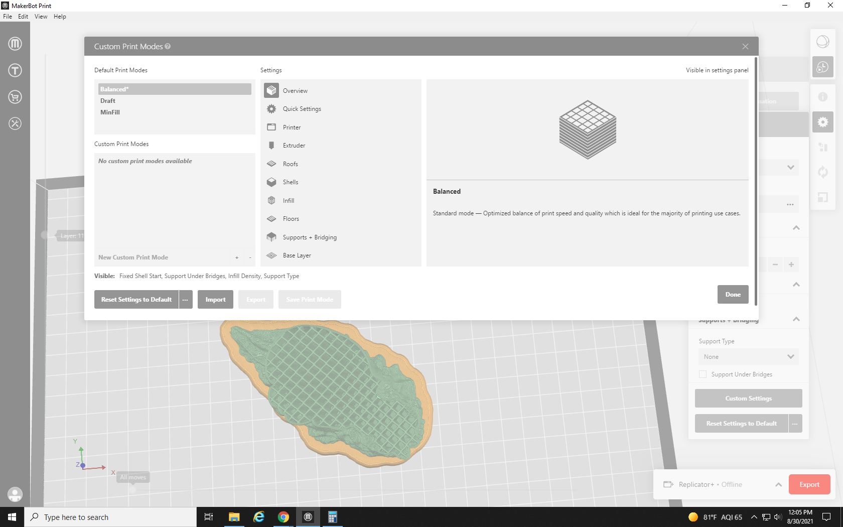
The first section of the Custom Print Settings to open up is the Overview tab. This section allows you to pick from default or saved “custom print modes,” which are just preset settings arrangements. We will keep this in balance, which has the highest base quality, and tweak our settings from there.
Our next tab is the “Quick Settings” tab. Here, MakerBot Print collects the settings that people change the most often. These settings are also in their own separate tabs, but we will cover them here for quick reference. The first option is the base layer. The base layer is the material (seen in yellow on the previewed print) that goes between the model and the print bed.
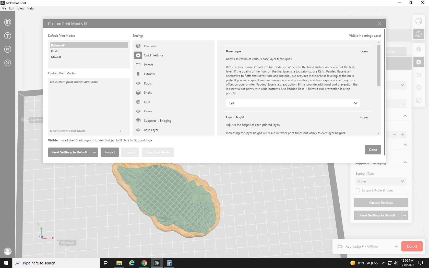
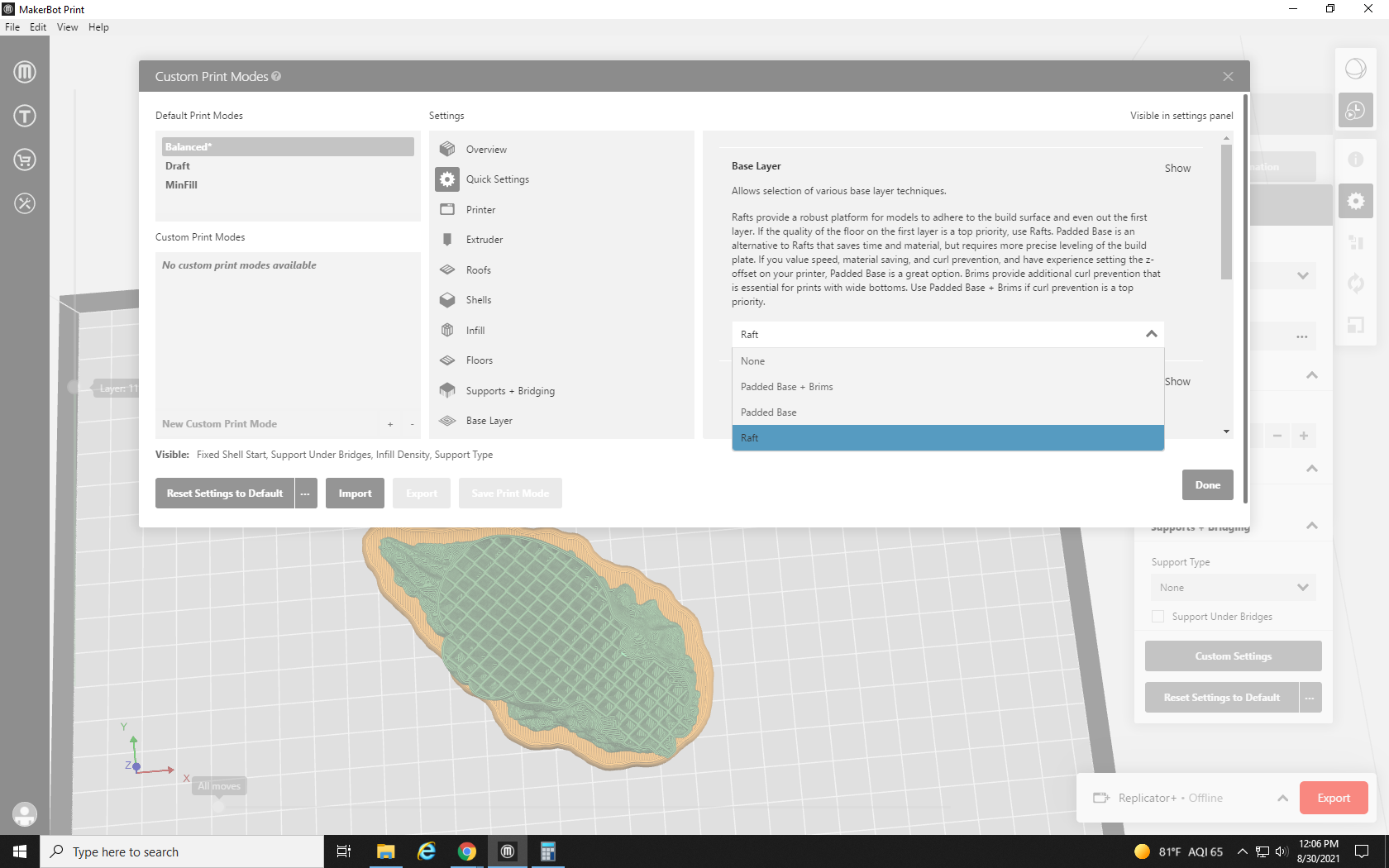
Other slicers often have options like rims (which just make a series of lines around the area that the print touches the bed to keep it from slipping around), but in MakerBot Print we are limited to Raft or Padded Base options. A padded base is a large, non-removable base on the bottom of the print, like the bottom of a carved bust. A raft is removable — we always go with the raft.
Next, we look at the layer height. This determines the height of each layer of the print. A larger layer height will print faster, and use less material, but will sacrifice some detail. A lower layer height takes more time, and uses more material, but can sometimes achieve greater detail. Our standard layer height is 0.2mm, which is pretty much the standard resolution for FDM 3D printers. We can go as low as 0.1mm, but in doing so have not noticed a great improvement in detail over .02mm.
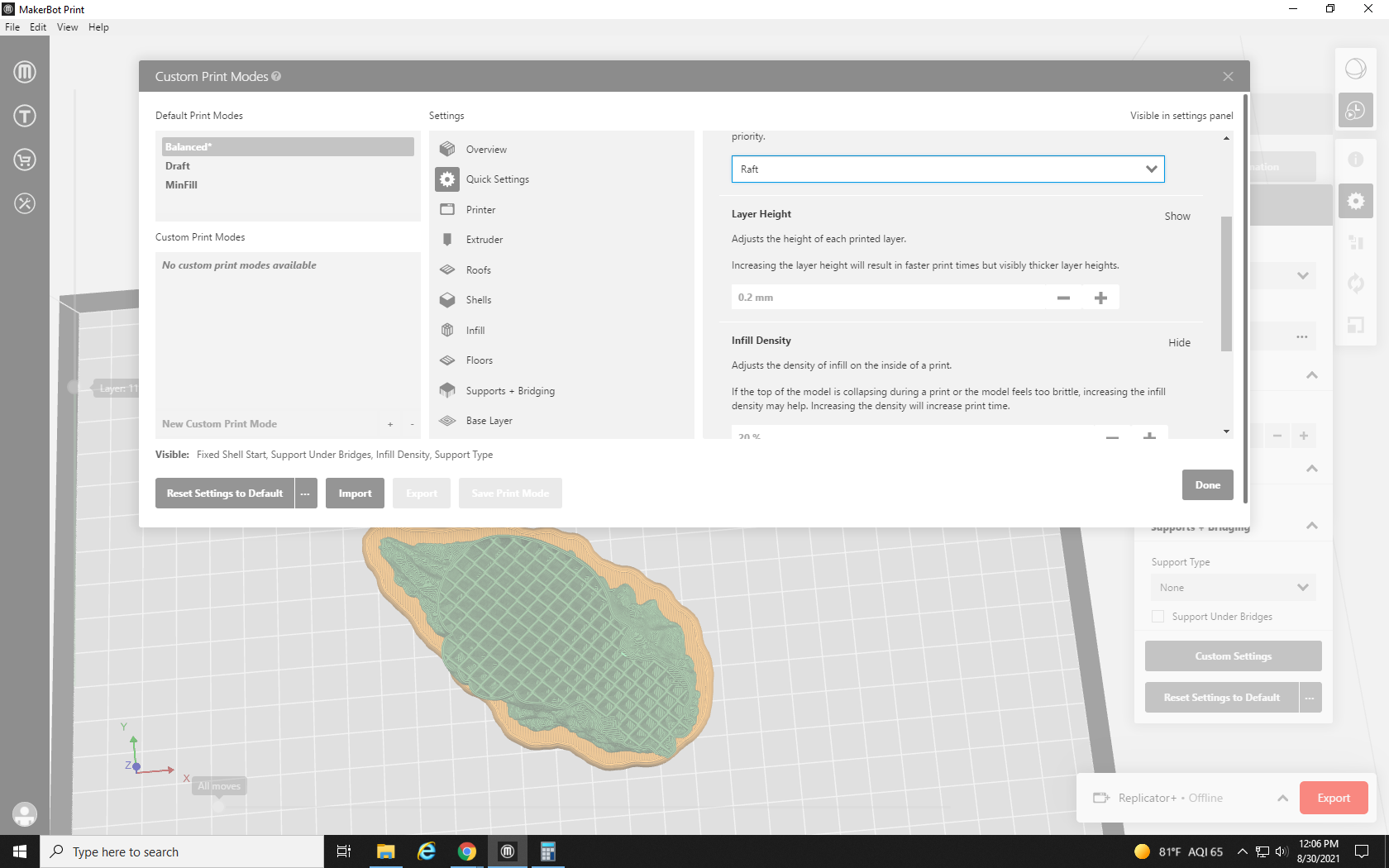
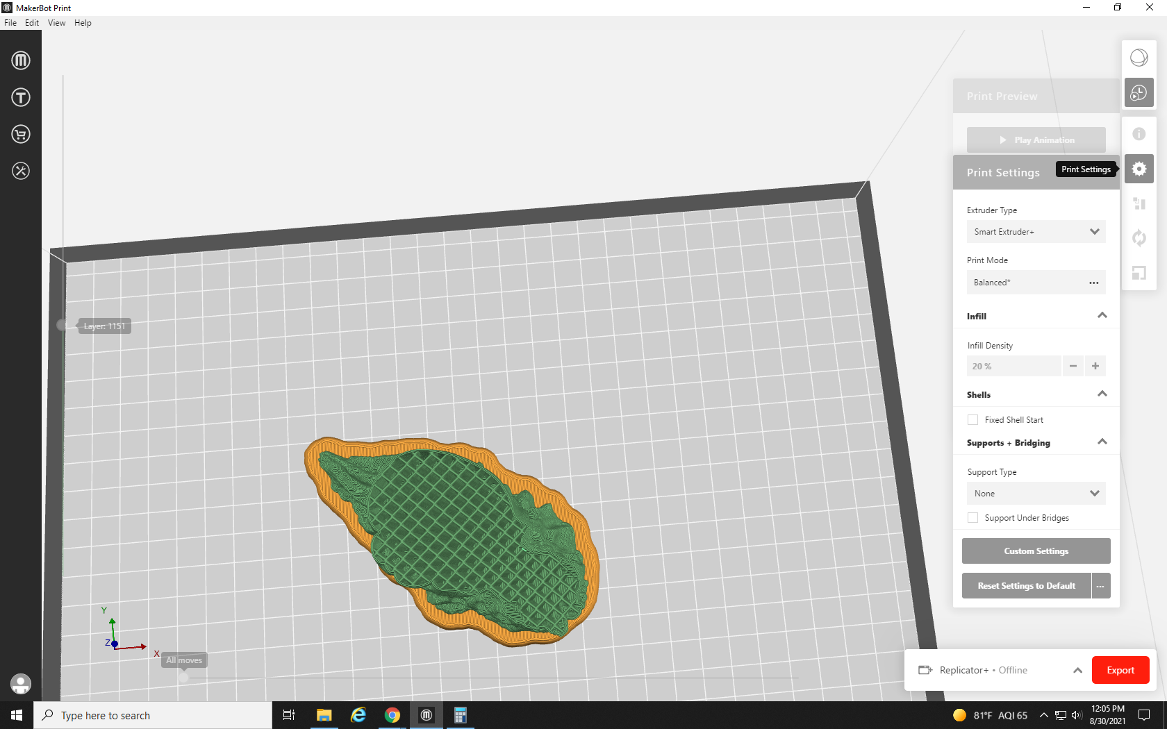
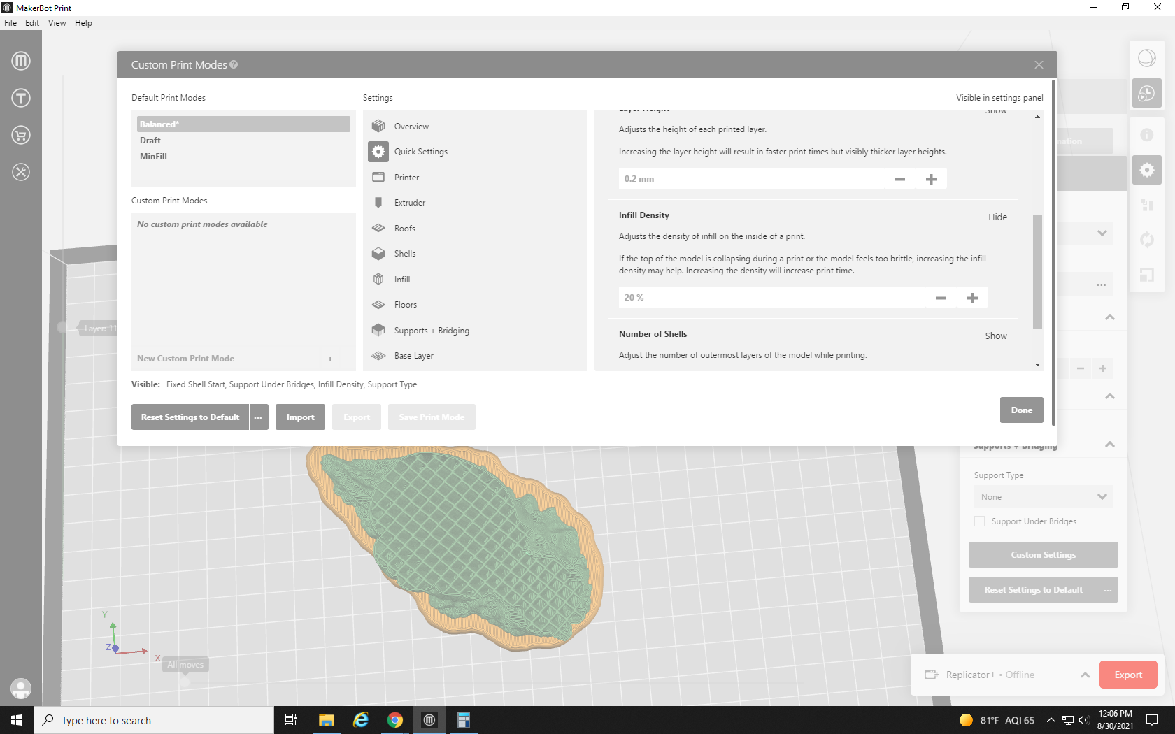
Next we have Infill density. The infill, as mentioned in previous tutorials, is the pattern of material that fills the inside of a model. The crisscross pattern inside of the print seen below is its infill. The infill density is a % that determines how solid the object would be. 100% and the entire print would be solid PLA, 0% and it would be a hollow shell. Increasing the infill density increases the strength and durability of the print, but increases print time and material use as well. Our default infill density is 20%, but when adjusting a model to lower its material use or increase its durability, this is the first setting we change. I want a pretty tough little print, but don’t need a solid hunk of plastic, so I’ll try it at 33%.
Our next setting, and the final setting in our Quick Settings tab is the Number of Shells drop down. What we would think of as the outside of the model the printer would call the outer shell. As the printer draws the object layer by layer, it first draws an outline of the print, and then the infill pattern within it. The number of shells dictates how many layers thick each outline is.

The drop-down goes from 1 shell to 10 shells. The recommended number of shells and our default number is 2, but for projects that need more strength, we go up to 5, or all the way to 10 for models we want to be essentially solid. As I’m sure you have guessed by now, this increase in durability comes at the cost of an increase in material use for a print. Optimizing the settings for a free print is a sort of balancing act between size, durability, and material cost. I want this Snailien to be as tough as the real thing, so I’m going to increase its durability and add 3 Shells.
Our next tab, the Printer tab, has only two settings: Purge Early End and Travel Speed. Purge Early End turns on (or off) the early ending of the “purge tower” through the entire print. A purge tower is a structure within the print where some extra filament is deposited to allow each layer to cool for longer. It is only necessary on very small prints, so we can usually turn on the Early End feature to save a bit of material. Travel Speed changes the speed the printer head moves when it is not printing. It can be increased to shorten the time it takes to print, but if it’s turned up too high, it could cause the printer to shake a bit and knock the print off the build plate. We leave the travel speed alone. It’s pretty quick as is.

The next tab is the Extruder tab. This contains adjustments to the hot end of the 3D printer.
Our first setting is the Extruder Temperature. This determines how hot the extruder gets. Too hot, and the PLA will get too soft and cause “stringing”. Stringing is when small, web-like strings of plastic stretch between the areas of the model that the print head moves between. Not hot enough and the PLA will be too hard to extrude, resulting in underextrusion. Underextrusion causes layers to be too thin, and makes the model extremely weak because the PLA is not being pressed into the previous layer. An underextruded print can be peeled apart layer by layer like a phyllo dough, or easily crushed in a fist like a honeycomb. Different filaments and materials call for different extruder temperatures. The Prusament PLA we are currently using strings at 215° C. so we are currently printing at 211° C. Previous filaments have had to be as high as 217° C to avoid underextrusion.

The next setting deals with the Extruder Retraction Distance. Before the print head moves between two points that it is not printing in between, it sucks the filament back up. Not retracting enough causes stringing, but retracting too much shortens the lifespan of the print head. We leave this one alone at 0.5mm.

Next, we move on to the Roofs tab. These options dictate how thick the top layer of the structure is. Roof Solid Thickness adjusts how thick the inside of the roof is, while Roof Surface Thickness adjusts the surface layer of the roof’s thickness. These can normally be left alone since we can just increase infill and number of shells to increase strength, but every once in a while you may come across a model that doesn’t quite seal along the top. Holes like this can usually be seen in the preview of the print and can be remedied by increasing the roof thickness.

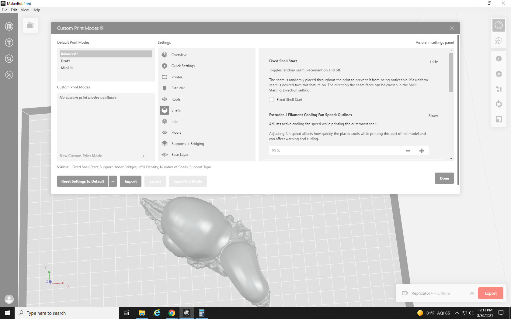
Now we move on to the Shells tab. The Shells tab is full of options for adjusting the shell of the model, some of which we have covered, and some of which we haven’t. Our first two settings are Fixed Shell Start and Cooling Fan Speed: Outlines.” Fixed shell start lets you toggle whether the layers of shell start at random points each layer, or one on top of each other like a seam. Sometimes, a layer’s starting point can leave a small wart of PLA, so for highly detailed prints that have a clear “backside” that won’t be seen, it makes sense to turn on the fixed start. Later on, we will find the setting to choose the location of the seam based on its angle. Most prints, however, are easiest when left with a random shell start.
Cooling Fan Speed is another option that depends on your filament brand and the environment around your printer. When layers cool too slowly, or too quickly, it can cause Warping. Warping is most prevalent in large flat areas such as the raft. Warping occurs when one part of the print, a far corner for instance, cools before the rest of it. This causes the area that cooled first to contract and pull upward. It can result in malformed prints and rafts that can’t be removed. At Re3D we use a DIY plexiglass box to cover the printer when it’s working. This protects it from drafts and temperature shifts in the room but also can make the area immediately around the printer even hotter. Usually, we leave the outline cooling fans on, but turn off the base cooling fans, which we’ll discuss later.
Our next two settings are the Extruder Speed and the Shell Starting Direction. The Extruder Speed controls how fast the print head moves when it’s printing the shells. For extremely detailed prints, this speed can be lowered. The print will take longer, but use the same amount of material with a better look to the surface. Conversely, if you are printing a big part that doesn’t have to be pretty, you can save some time by cranking the speed up. However, going too fast will lose some detail, and risks knocking your print off the build plate (in the same manner as the Travel Speed).
Shell Starting Direction is how you select where the seam will be if you enabled the Fixed Shell Start option. The position is based on the angle formed between a line from the center of the model straight out toward you, and the seam. To put the seam in the front you would set it to 0, the back would be 180, and 90 and 270 correspond to the right and left of the build plate respectively. However, if you leave Fixed Shell Start unchecked and disabled, you can ignore this setting completely.
For our final two settings in the Shells tab, we have Layer Height and Number of Shells. The description of both of these settings can be found above in the Quick Settings tab section.
Our next tab is the Infill tab. This contains settings that let you change the shape and density of the Infill, among other things. The first two settings control the print speed during various infill densities. The first adjusts the speed when the infill is densely packed, and the second is used when the print has a bit of space between the lines. Both can go pretty fast without messing up detail and there is little reason to turn this down from its default. The reason this is separated into two speeds is that the print head is more likely to knock the print off the build plate in a densely printed area. This way they can be tweaked separately if you’re in a rush. We leave these alone for the most part.
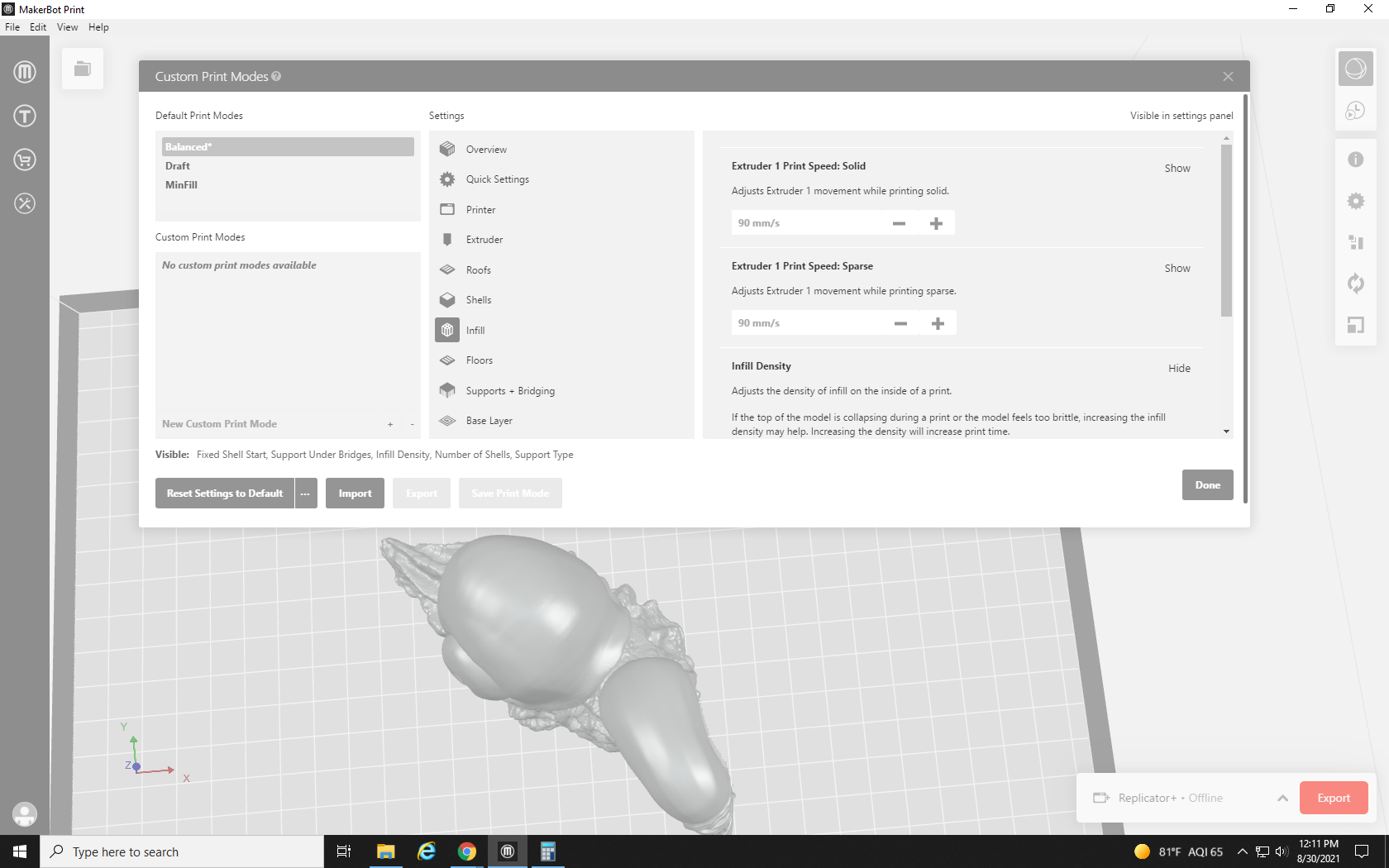
Next, we have Infill Density, which is the same as the version explained above in the Quick Settings section. The setting for Infill Pattern is interesting, though: it lets you change the pattern of the infill.
The drop-down shows the types of infill available. The Diamond Fast Fill is the default, and for the most part, all of the patterns are equally structurally sound. They simply change the appearance of a part of your print you hope to never see. Some of them are pretty amusing though, and I like to use them as easter eggs in prints. When a cat-themed print request comes through, you can bet I’m using the Cat pattern infill, which looks like a pattern of cats. The Sunglasses, Shark, and Donut patterns are also personal favorites.
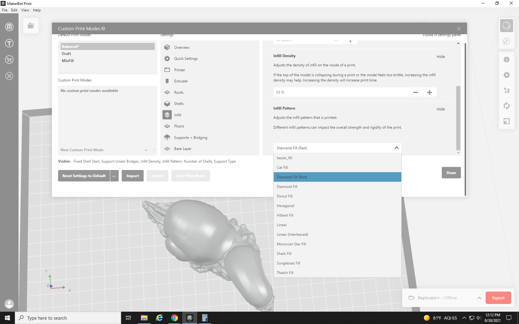
This desk decoration is so hot it’s gotta wear shades, so I’m going with the sunglasses infill pattern.
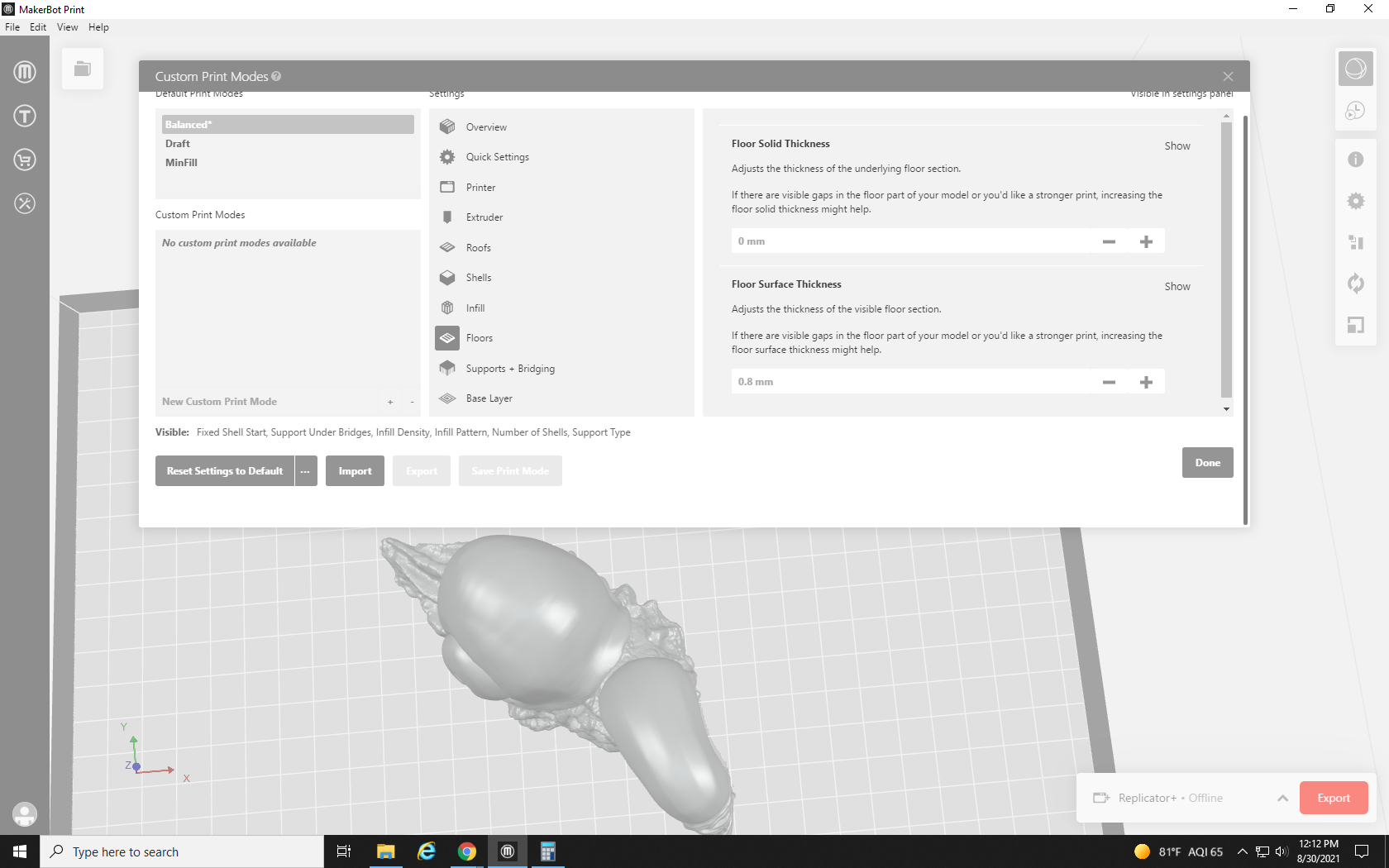
Our next tab of settings is the Floors tab. These settings, the Floor Solid and Surface Thickness settings, are the same as their equivalent Roof settings. They adjust how thick the bottom layers of the print are. Unless there is a problem with the seal on the bottom of the print, it’s fine to leave these be.
Our next tab is the Supports + Bridging tab. This is a tab that we frequent pretty often. The first option, Support Under Bridges, changes whether or not support material is generated under an area that has nothing under it but is connected to two points that do, like the apex of the arch under an arch bridge, or the inseam of an action figure. It’s best to use your own judgment here. If the curve of the arch is shallow, it may be able to bridge on its own, but if it’s a sharp incline it probably won’t. These settings are a bit of a balancing act. Using more support than you need wastes filament, is a pain to remove, and risks damaging the print when removing it; not enough support and the area under the bridge or overhang will collapse and sag.
Support Angle lets you adjust the angle where the printing process begins to generate support. 0 will put support over everything (a flat plane), and 90 (a vertical plane) will not generate any support in the print. This setting often takes several adjustments: setting it, looking at the preview to see if the supports look sufficient (or if there are too many), and coming back to readjust and try again.

Next is Support Generation Outset. This determines how far past the edge of the model the support will reach. This one is fine to leave alone, but can be turned down to save material, or up to support heavier prints.
Our next setting is the Support Density. It determines how close the support structures are to each other. Dense supports are more effective, but harder to remove and may damage fine details. Much like the Support Angle setting, this one often takes a few guesses, checks, and adjustments to get right for each unique print.
Support to Model Spacing, our next setting, determines how much empty space is left between the support structure and the model it’s supporting. If the supports are not working, this can be turned down, but they will be harder to remove. Conversely, increase the spacing to make supports easier to remove, but don’t go too high, because it becomes more likely that the supports won’t do their job if you do. Small tweaks between prints to find your personal preference and your printer’s tolerance are recommended.
For our final setting in the Support tab, we come to the Support Type. As mentioned above, the only options in MakerBot Print are Breakaway and None. Due to the overhanging face of the Snailien, we will need to turn breakaway supports on.
Then we reach the final tab for our Settings, the Base Layer setting. The first setting is the Base Layer Type, with a choice of Raft or Padded base, as described in the Quick Settings section.
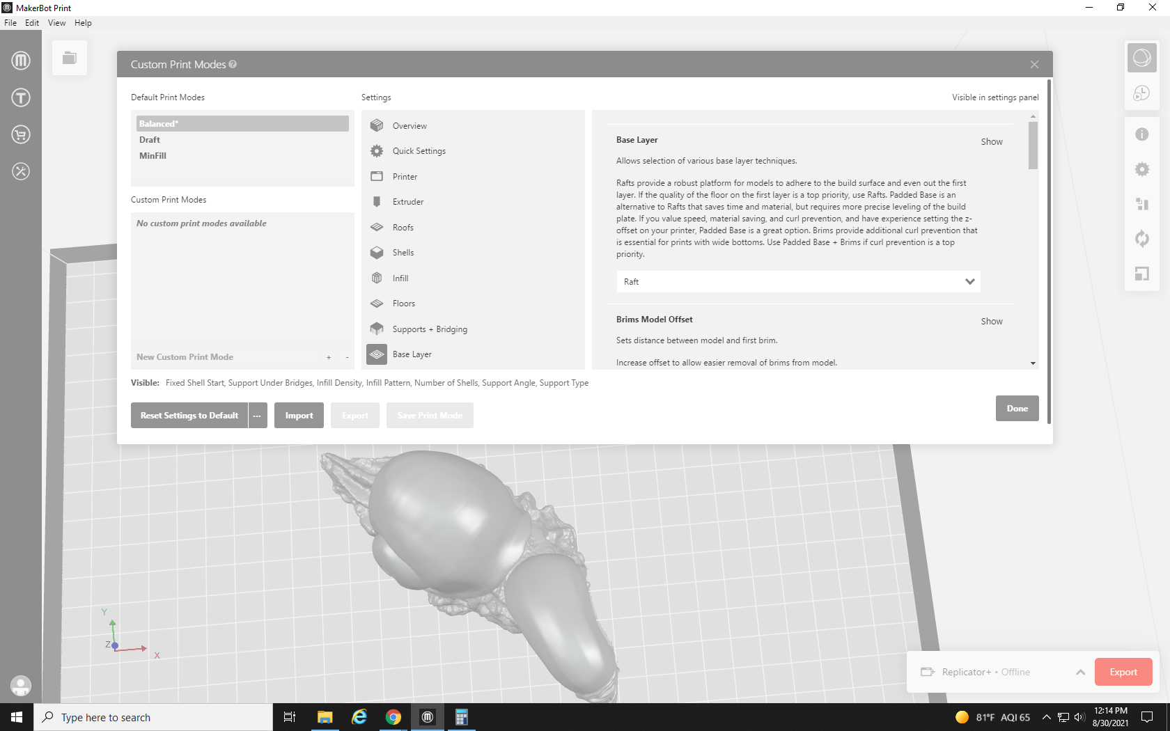
Next are the Brim Model Offset and the First Layer Cooling Fan settings. The Brim Offset determines how far past the outline of the base the printer will draw the brim, but it is not applicable when using rafts. Because of the heat concentration in our printer, I often turn the First Layer Cooling Fan completely off (0%) to avoid warping. Adjust this to fit the environment around your printer.
The next settings are the First Layer Print Speed and the Raft Base Cooling Fan. The first layer of your print is the foundation that everything will rest on, so it’s best to keep the speed of this layer nice and slow. Just like the base layer, I usually turn the Raft Cooling Fan to 0% as the raft is the widest, flattest portion of the print and is most likely to warp, but this should be adjusted to your printer’s physical environment. When there is an issue with a print, “guess and check” is the name of the game with 3D printing.
Next, we have the settings for the Print Speed of the Raft or Base, and the Number of External Brims. Much like the other print speeds, this one is kind of self-explanatory, the raft/base print speed is the speed the print head moves when printing the raft or base layers. This is the only portion that directly touches the build plate, so it should be really slow. Although we don’t use brims and padded bases at Re3D, the number of external brims (counting outward from the first brim) controls the number of outlines around the base of the model the printer will make. If you do not have a raft, brims can help keep a print secured to the build plate.
The number of external brims is the same as the number of internal brims but counts inward from the first brim. So a print with 5 external and 5 internal brims would have 9 total brims. Brim 1 of each set of 5 would overlap as the same brim in the center of the print. Raft to Model Shell vertical offset controls how much space is left between the top layer of the raft, and the bottom layer of the model. If this number is too high, the model will fall off the raft and the print will fail, but if it’s not high enough you will not be able to remove the raft without breaking the model. I usually turn this up to around 0.3mm for (relatively) easy raft removal.

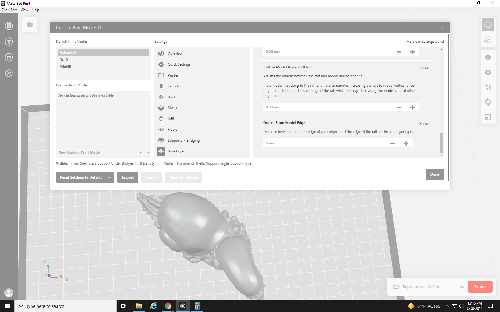
Our final two settings are the Raft to Model Vertical Offset and the Outset From Model Edge. The Raft to Model Vertical Offset is very similar to the Raft to Model Shell Vertical Offset, but rather than controlling the difference between the top layer of the raft and the bottom layer of the model, this one controls the distance between the top layer of the raft and the internal layer of the model, which is directly touching the inflow. This number should be kept a bit higher than the Raft to Model Shell Vertical Offset. I tend to keep it at 0.35 mm. Outset from the model edge controls how far past the model, in the horizontal plane, the raft or base goes. The default setting of 4mm is usually fine, but if you’re trying to save material on a large flat print, it can be turned down to 2mm. Any lower and the raft will become difficult to remove. Objects that require a lot of support, or balance precariously, may benefit from the enhanced stability extending this offset can offer.
With our scale adjusted and our settings optimized for the print, we can go ahead and click OK, and then Print Preview, to see how the slicer processes our print and make sure it’s still ready to request.
OH NO! Now it’s 89.25 Grams?! That’s more than the print limit! But it was only 50 or so grams before I tweaked these settings. What happened?
One thing that contributed to the increase in material used is the infill amount that we turned up to 33%. Notice the sunglasses pattern that repeats on the inside of the model? Pretty cool, right? That’s the infill pattern we changed. If you look closely at the outline, you can see that there are three layers to it, those are our three shells.
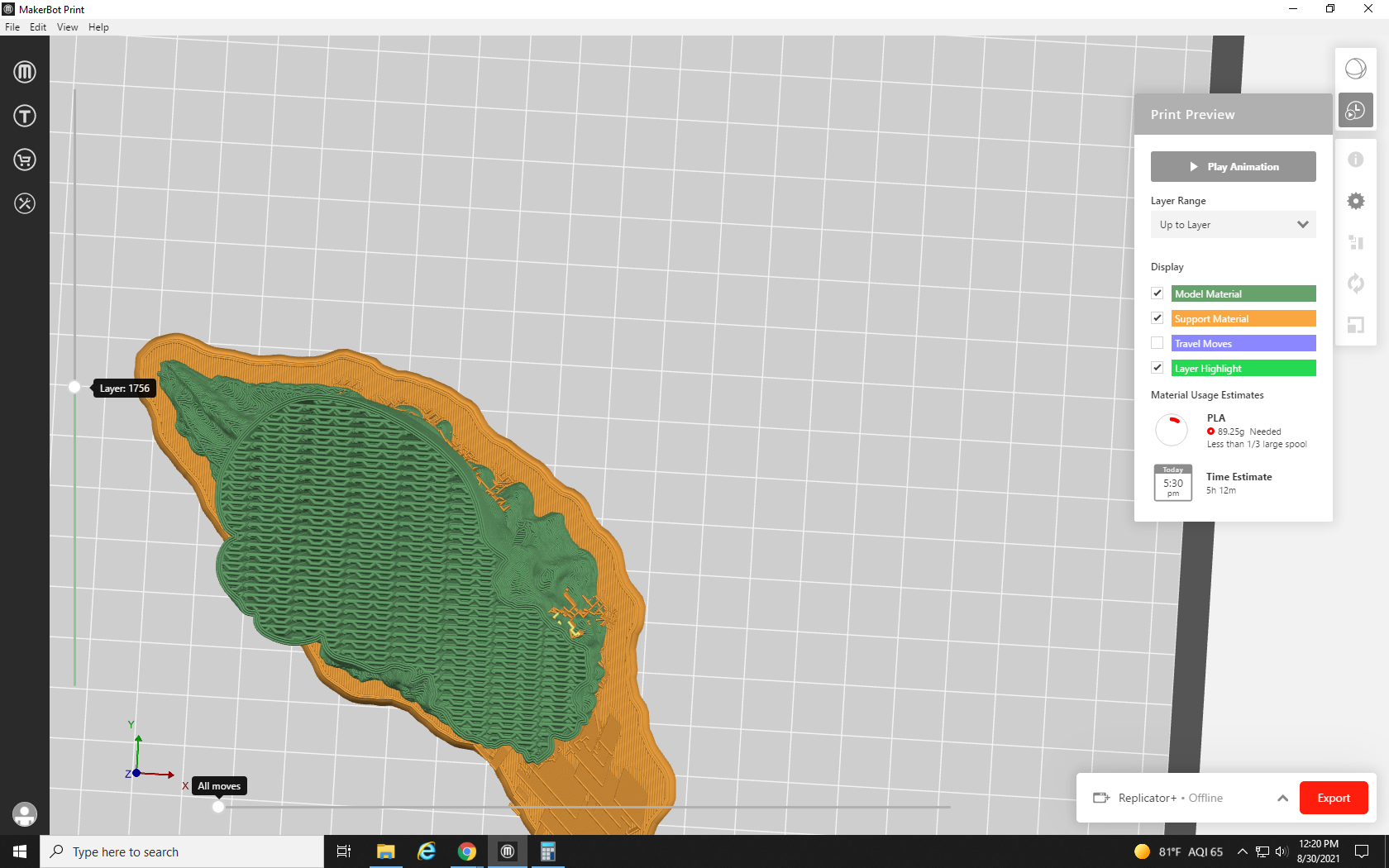
One of the biggest contributors to the increase in material used is the supports. That big old cloud of yellow under the head. Without it, the head would collapse while printing, but it looks like a lot of extra material.
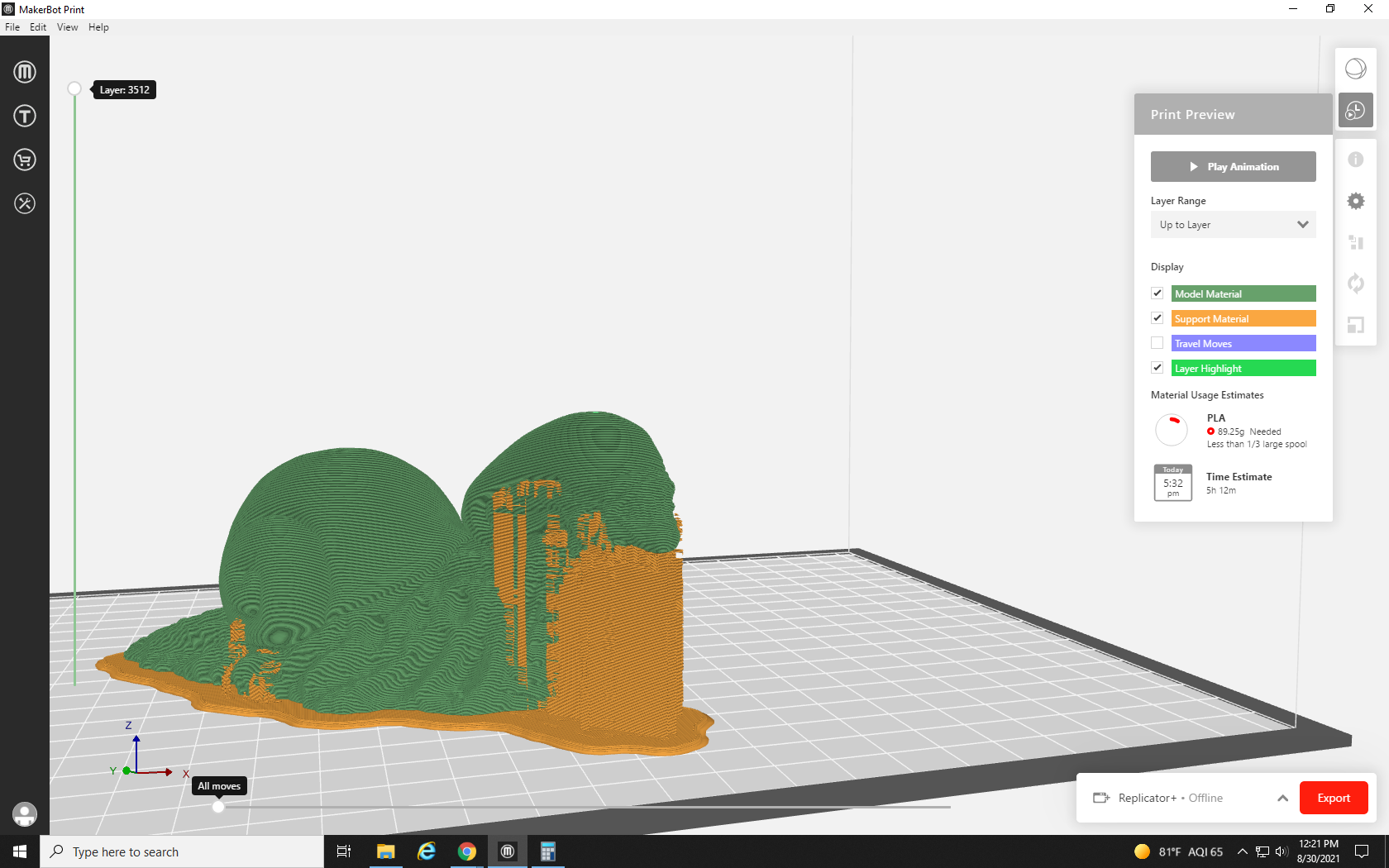
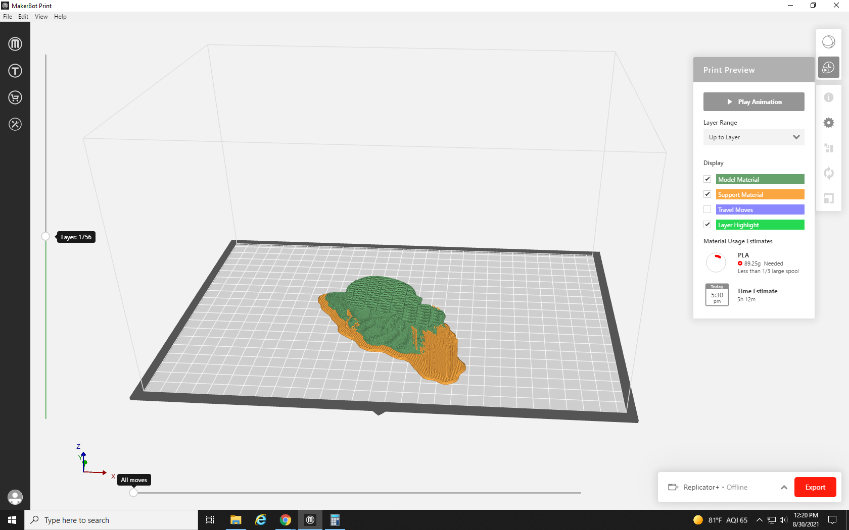
Although, if you take a cross-section part way down it and look down (see Fig. 29), you can see that the density of support material is actually pretty low, so I don’t think we want to adjust that to save material.
Clicking the gear icon to go back to the Settings, we no longer have to use the Custom Settings button, because every setting we changed is now listed in its Quick Access toolbar. Since we can’t sacrifice the support material, we’ll have to cut back on our durability.
We adjust the infill density back down to 20% and reduce the number of shells to 2. It will still be strong enough, about as strong as an average print.
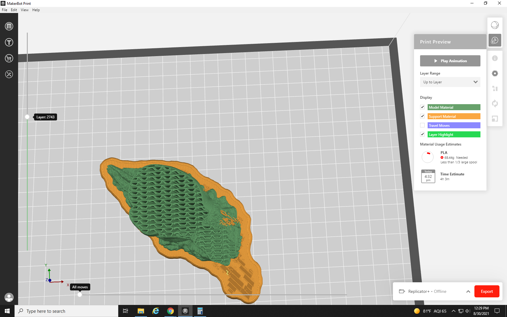
After reprocessing, we are now in much better shape. Using only 68 grams of material (a reduction of almost 20 grams). We can now submit this request for a free Snalien.
When we look down at the cutaway, we can now see that the walls are a little bit thinner, reflecting our decrease to two shells. Additionally, the sunglasses in the infill pattern have gotten larger and more spaced out, reflecting our lowered infill density, but the model is still far from hollow.
Thanks for following along with our sixth and final tutorial. You now know enough to download just about any print you want, adjust its placement and scale on the build plate, and adjust the printer’s settings to get the best results possible. You are ready to 3D print any and all of your plastic doodad needs. But this is, of course, only a primer on the basics of 3D printing — there’s so much more knowledge about 3D printing to learn, from machine maintenance (such as cleaning clogged print heads, replacing parts, and performing the dreaded “atomic pull” to clean out a print head) to 3D design with advanced software such as Blender. As a hobby or a form of manufacturing, 3D printing can be challenging but ultimately extremely rewarding, and we here at Re3D wish you luck in your quest for the perfect print!
The bottom-most layer of the raft touching the build plate
Term used to describe the printer head and the extrusion nozzle as a single unit
A 3D printing error wherein small web-like strings of plastic stretch between the areas of the model that the printer head moves between to print
